– 9 –
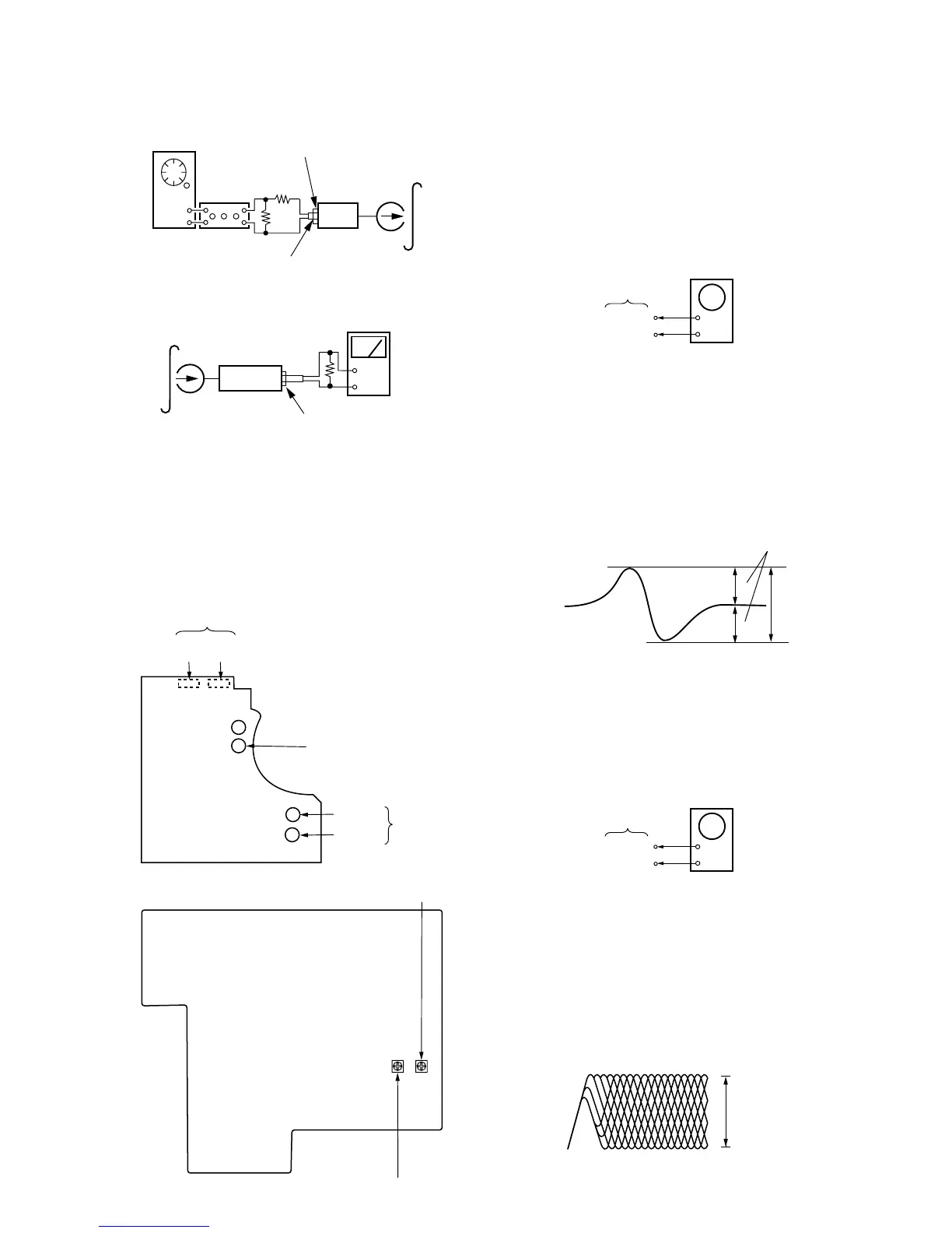
Record Level Adjustment
Procedure :
1. Mode : Record
set
AF OSC
attenuator
blank tape
CS-123
600
Ω
10 k
Ω
315Hz 72.3mV (–20.6dB)
TAPE IN
2. Mode : Playback
set
level mete
+
–
recorded
portion
47 k
Ω
TAPE OUT
3. Confirm playback the signal recorded in step 1 become adjust-
ment level as follows.
4. If these levels do not adjustment level, adjust the RV111
(L-CH) and RV211 (R-CH) to repeat step 1 and 4.
Adjustment Level :
TAPE OUT level : – 26± 0.5dB (36.7 to 41.1mV)
Adjustment Location : MAIN board.
[AUDIO BOARD] (Conductor side)
Record Bias
(R) (L)
RV22 RV12
RV71 (NORMAL) Tape speed
RV21(R)
RV11(L)
Playback Level
[MAIN BOARD]
(Component side)
RV111 : Record level
RV211 : Record level (R-CH)
CD SECTION
Note :
1. CD Block basically constructed to operate without adjustment.
Therefore, check each item in order given.
2. Use YEDS-18 disc (3-702-101-01) unless otherwise indicated.
3. Use the oscilloscope with more than 10MΩ impedance.
4. Clean an object lens by an applicator with neutral detergent when
the signal level is low than specified value with the following
checks.
S-Curve Check
+
–
BD board
TP (FE)
TP (VC)
oscilloscope
Procedure :
1. Connect oscilloscope to test point TP(FE) and BD board.
2. Connect between test point TP (FEI) and TP (VC) by lead wire.
3. Turned Power switch on.
4. Put disc (YEDS-18) in and turned Power switch on again and
actuate the focus search. (Actuate the focus search when disc
table is moving in and out.)
5. Check the oscilloscope waveform (S-curve) is symmetrical be-
tween A and B. And confirm peak to peak level within
3 ±1Vp-p.
A
B
within 3
±
1Vp-p
symmetry
6. After check, remove the lead wire connected in step 2.
Note : r Try to measure several times to make sure that the ratio of
A : B or B : A is more than 10 : 7.
r Take sweep time as long as possible and light up the bright-
ness to obtain best waveform.
RF Level Check
+
–
BD board
TP (RF)
TP (VC)
oscilloscope
Procedure :
1. Connect oscilloscope to test point TP (RF) on BD board.
2. Turned Power switch on.
3. Put disc (YEDS-18) in and playback.
4. Confirm that oscilloscope waveform is clear and check RF sig-
nal level is correct or not.
Note :
Clear RF signal waveform means that the shape “
◊
” can be
clearly distinguished at the center of the waveform.
level : 1.2 Vp-p
+0.25
–0.20
VOLT/DIV : 200mV
TIME/DIV : 500nS
RF signal waveform