EasyManua.ls Logo

Sony WM-D6 - Page 13

Sony WM-D6
32 pages
Print Icon
To Next Page IconTo Next Page
To Previous Page IconTo Previous Page
Loading...
SECTION
3
ADJUSTMENTS
PRECAUTION
_
‘
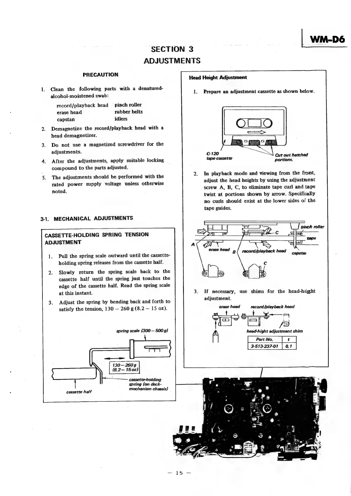
Head
Height
Adjustment
1.
Clean
the
following
parts
with
a
denatured-
alcohol-moistened
swab:
1.
Prepare
an
adjustment
cassette
as
shown
below.
record/playback
head
_
pinch
roller
erase
head
rubber
belts
capstan
idlers
2.
Demagnetize
the
record/playback
head
with
a
head
demagnetizer.
3.
Do
not
use
a
magnetized
screwdriver
for
the
adjustments.
Cut
out
hatched
portions.
4.
After
the
adjustments,
apply
suitable
locking
tape
cassette
compound
to
the
parts
adjusted.
5.
The
adjustments
should
be
performed
with
the
rated
power
supply
voltage
unless
otherwise
noted.
2.
In
playback
mode
and
viewing
from
the
front,
adjust
the
head
heights
by
using
the
adjustment
screw
A,
B,
C,
to
eliminate
tape
curl
and
tape
twist
at
portions
shown
by
arrow.
Specifically
no
curls
should
exist
at
the
lower
sides
of
the
tape
guides.
3-1.
MECHANICAL
ADJUSTMENTS
CASSETTE-HOLDING
SPRING
TENSION
ADJUSTMENT
Pull
the
spring
scale
outward
until
the
cassette-
holding
spring
releases
from
the
cassette
half.
2.
Slowly
return
the
spring
scale
back
to
the
cassette
half
until
the
spring
just
touches
the
edge
of
the
cassette
half.
Read
the
spring
scale
at
this
instant.
3.
Adjust
the
spring
by
bending
back
and
forth
to
satisfy
the
tension,
130
—
260
g
(8.2
—
15
02).
If
necessary,
use
shims
for
the
head-hight
adjustment.
erase
head
record
{playback
head
a
eee
fd
=]
/s
fy
head-hight
adjustment
shim
[PartNo
*]
[ssra2a701
|
a
|
spring
scale
(300
—
500g)
|
—————
a
130
—
2609
(8.2—150z}
cassette-holding
spring
(on
deck-
mechanism
chassis)
—
cassette
half