EasyManua.ls Logo

Sony WM-D6 - Electrical Adjustments

Sony WM-D6
32 pages
Print Icon
To Next Page IconTo Next Page
To Previous Page IconTo Previous Page
Loading...
|
WM-D6
WM-D6
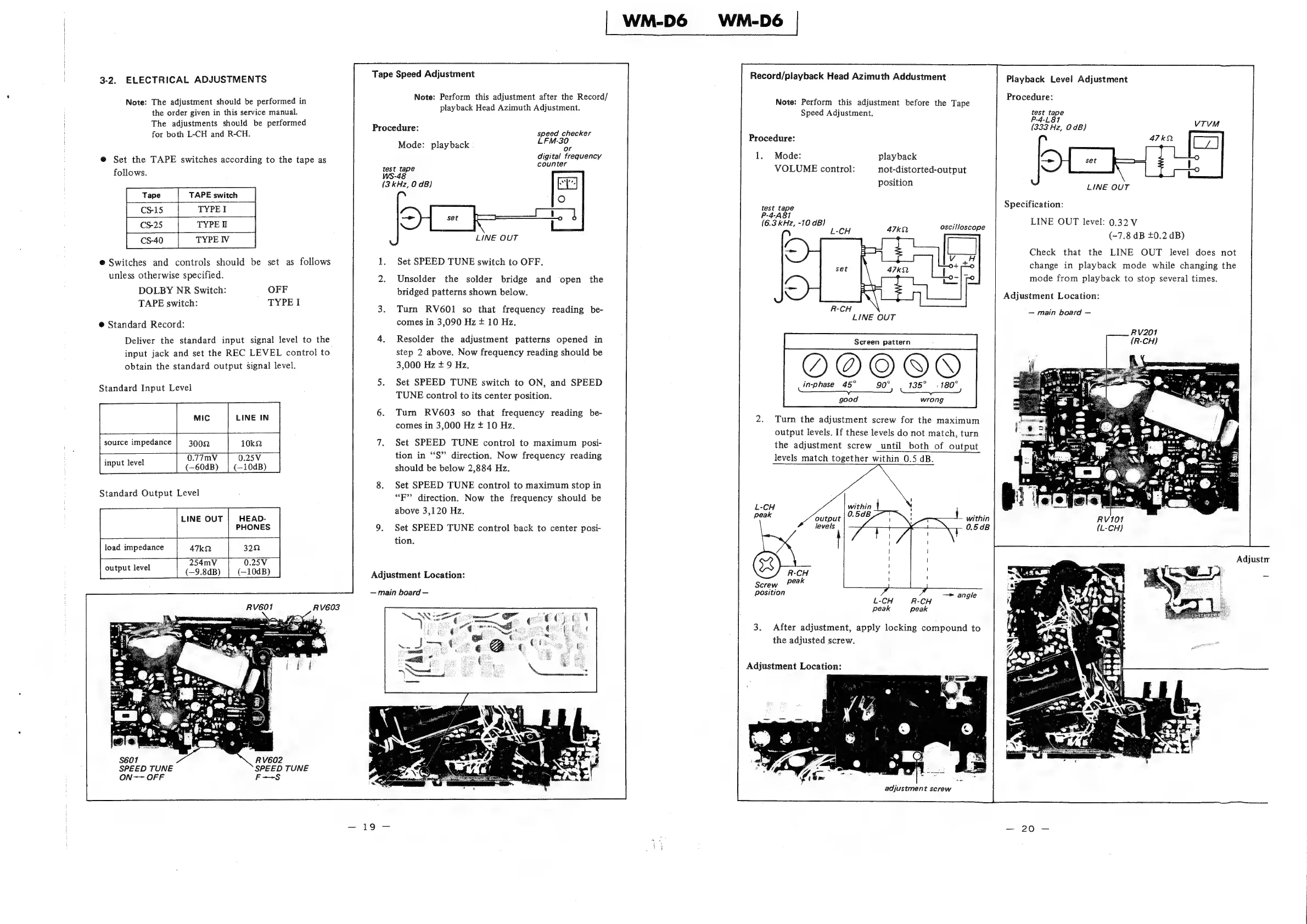
3-2.
ELECTRICAL
ADJUSTMENTS
Tape
Speed
Adjustment
Note:
Perform
this
adjustment
after
the
Record/
playback
Head
Azimuth
Adjustment.
Note:
The
adjustment
should
be
performed
in
the
order
given
in
this
service
manual.
The
adjustments
should
be
performed
for
both
L-CH
and
R-CH.
Procedure:
speed
checker
LFM-30
Mode:
playback
-
or
digital
frequency
counter
@
Set
the
TAPE
switches
according
to
the
tape
as
follows.
Tape
TAPE
switch
TYPE
I
e
Switches
and
controls
should
be
set
as
follows
unless
otherwise
specified.
DOLBY
NR
Switch:
OFF
TAPE
switch:
TYPE
I
test
tape
WS-4
(3
kHz,
0
dB)
8
ae
pe
fe
k
LINE
OUT
1.
Set
SPEED
TUNE
switch
to
OFF.
2.
Unsolder
the
solder
bridge
and
open
the
bridged
patterns
shown
below.
3.
Turn
RV601
so
that
frequency
reading
be-
comes
in
3,090
Hz
+
10
Hz.
4.
Resolder
the
adjustment
patterns
opened
in
step
2
above.
Now
frequency
reading
should
be
3,000
Hz
+
9
Hz.
5.
Set
SPEED
TUNE
switch
to
ON,
and
SPEED
TUNE
control
to
its
center
position.
@
Standard
Record:
Deliver
the
standard
input
signal
level
to
the
input
jack
and
set
the
REC
LEVEL
control
to
obtain
the
standard
output
signal
level.
Standard
Input
Level
6.
Turn
RV603
so
that
frequency
reading
be-
comes
in
3,000
Hz
+
10
Hz.
7.
Set
SPEED
TUNE
control
to
maximum
posi-
tion
in
‘“S”
direction.
Now
frequency
reading
should
be
below
2,884
Hz.
8.
Set
SPEED
TUNE
control
to
maximum
stop
in
“F”
direction.
Now
the
frequency
should
be
above
3,120
Hz.
9.
Set
SPEED
TUNE
control
back
to
center
posi-
tion.
LINE
IN
source
impedance
10kQ
:
0.25V
input
level
(—104B)
Standard
Output
Level
load
impedance
output
level
Adjustment
Location:
—
main
board
—
SPEED
TUNE
F--S
SPEED
TUNE
ON-—
OFF
Record/playback
Head
Azimuth
Addustment
Playback
Level
Adjustment
Procedure:
Note:
Perform
this
adjustment
before
the
Tape
Speed
Adjustment.
wi
ie
A
(333
Hz,
0dB)
A
id
Procedure:
1.
Mode:
playback
i
VOLUME
control:
not-distorted-output
position
LINE
OUT
Specification:
LINE
OUT
level:
0.32
V
(-7.8
dB
+0.2
dB)
Check
that
the
LINE
OUT
level
does
not
change
in
playback
mode
while
changing
the
mode
from
playback
to
stop
several
times.
test
tape
P-4-A81
(6.3
kHz,
-10
dB)
L-CH
47kQ
oscilloscope
Adjustment
Location:
—
main
board
—
LINE
OUT
Screen
pattern
135°
=
180°
wrong
in-phase
45° 90°
good
Turn
the
adjustment
screw
for
the
maximum
output
levels.
If
these
levels
do
not
match,
turn
the
adjustment
screw
until
both
of
output
levels
match
together
within
0.5
dB.
within
0.5dB
R-CH
peak
Screw
position
—»
angle
L-CH
R-CH
peak
peak
3.
After
adjustment,
apply
locking
compound
to
the
adjusted
screw.
Adjustment
Location:
adjustment
screw