EasyManua.ls Logo

Sony WM-D6 - Page 18

Sony WM-D6
32 pages
Print Icon
To Next Page IconTo Next Page
To Previous Page IconTo Previous Page
Loading...
NM-D6
WM-D6
|
WM-D6
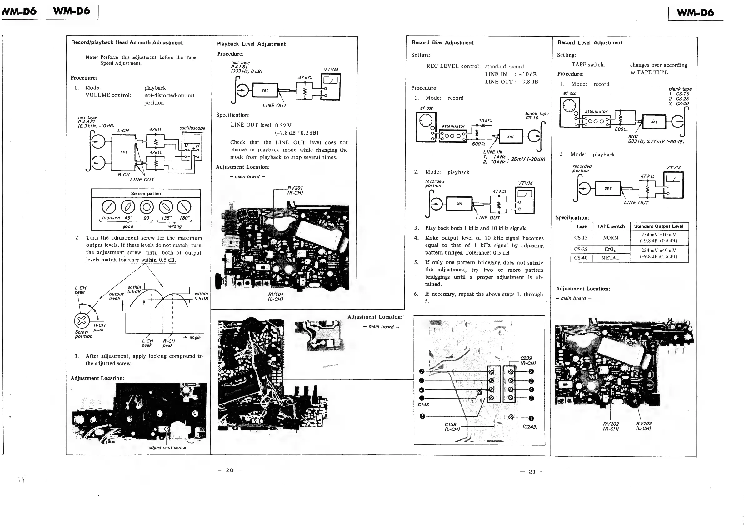
Record/playback
Head
Azimuth
Addustment
Playback
Level
Adjustment
Record
Bias
Adjustment
Record
Level
Adjustment
:
ing:
Setting:
Note:
Perform
this
adjustment
before
the
Tape
procedure
Setting
ing
Speed
Adjustment.
Dalat
REC
LEVEL
control:
standard
record
TAPE
switch:
changes
over
according
(333
Hz,
0a)
eM
LINE
IN
:-10dB
Brdceduye:
as
TAPE
TYPE
prsccane:
LINE
OUT:
-9.8
dB
1.
Mode:
record
:
Procedure:
;
blank
tape
1.
Mode
playback
ts
nes
blank
tap
VOLUME
control:
not-distorted-output
1.
Mode:
record
2
CS-25
position
LINE
OUT
f
*
ee
al
osc
attenuator
Specification:
oe
tape
O
eee
|
PAA!
10k2
5HO00
>
(6.3
kHz,
-10
dB)
LINE
OUT
level:
0.32
V
O}
_
attenuator
A,
a
(-7.8
dB
+0.2
dB)
TP
000
mic
333
Hz,
0.77mV
(-60dB)
Check
that
the
LINE
OUT
level
does
not
6002
change
in
playback
mode
while
changing
the
g
play
nging
rey
2.
Mode:
playback
mode
from
playback
to
stop
several
times.
2)
jottes
25mvV
(-30dB)
Adjustment
Location:
recorded
VTVM
2.
Mode:
playback
portion
R-CH
—
main
board
—
LINE
OUT
recorded
VTVM
portion
om
|
ser
|
LINE
OUT
in-phase
45° 90°
135°
180°
LINE
OUT
Specification:
good
wrong
254
mV
+10
mV
ee
Noee
(-9.8
4B
+0.5
dB)
CS-25
254
mV
+40
mV
CS-40
METAL
(-9.8
dB
#1.5
dB)
Play
back
both
1
kHz
and
10
kHz
signals.
4.
Make
output
level
of 10
kHz
signal
becomes
equal
to
that
of
1
kHz
signal
by
adjusting
pattern
bridges.
Tolerance:
0.5
dB
Turn
the
adjustment
screw
for
the
maximum
output
levels.
If
these
levels
do
not
match,
turn
the
adjustment
screw
until
both
of
output
levels
match
together
within
0.5
dB.
5.
If
only
one
pattern
bridgging
does
not
satisfy
the
adjustment,
try
two
or
more
pattern
bridggings
until
a
proper
adjustment
is
ob-
tained.
within
Adjustment
Location:
0.50B
output
6.
If
necessary,
repeat
the
above
steps
1.
through
levels
—
main
board
—
Adjustment
Location:
'
R-CH
—
main
board
—
peak
Screw
position
—»
angle
L-CH
R-CH
peak
peak
3.
After
adjustment,
apply
locking
compound
to
the
adjusted
screw.
Adjustment
Location:
RV202
RV102
(R-CH)
(L-CH)
adjustment
screw
S20
=.
DY.
ee