— 2 —
TABLE OF CONTENTS
Flexible Circuit Board Repairing
• Keep the temperature of the soldering iron aroud 270˚ C during
repairing.
• Do not touch the soldering iron on the same conductor of the
circuit board (within 3 times).
• Be careful not to apply force on the conductor when soldering
or unsoldering.
Notes on chip component replacement
• Never reuse a disconnected chip component.
• Notice that the minus side of a tantalum capacitor may be
damaged by heat.
SECTION 1
GENERAL
1. GENERAL ······································································ 2
2. DISASSEMBLY
2-1. Cabinet (REAR) ································································· 3
2-2. Main Board ········································································· 4
2-3. Lid, Cassette ······································································· 4
2-4. Mechanism Deck ································································ 5
2-5. “BELT” “MOTOR” “PINCH LEVER” “HEAD,
MAGNETIC” ····································································· 5
3. MECHANICAL ADJUSTMENT ······························ 6
4. ELECTRICAL ADJUSTMENT ································ 6
5. DIAGRAMS
5-1. Block Diagram ··································································· 7
5-2. Printed Wiring Board·························································· 9
5-3. Schematic Diagram ·························································· 11
5-4. IC Block Diagram ···························································· 13
6. EXPLODED VIEWS
6-1. Cabinet Section································································· 14
6-2. Main Board Section ·························································· 15
6-3. Mechanism Section-1 ······················································· 16
6-4. Mechanism Section-2 ······················································· 17
7. ELECTRICAL PARTS LIST ··································· 18
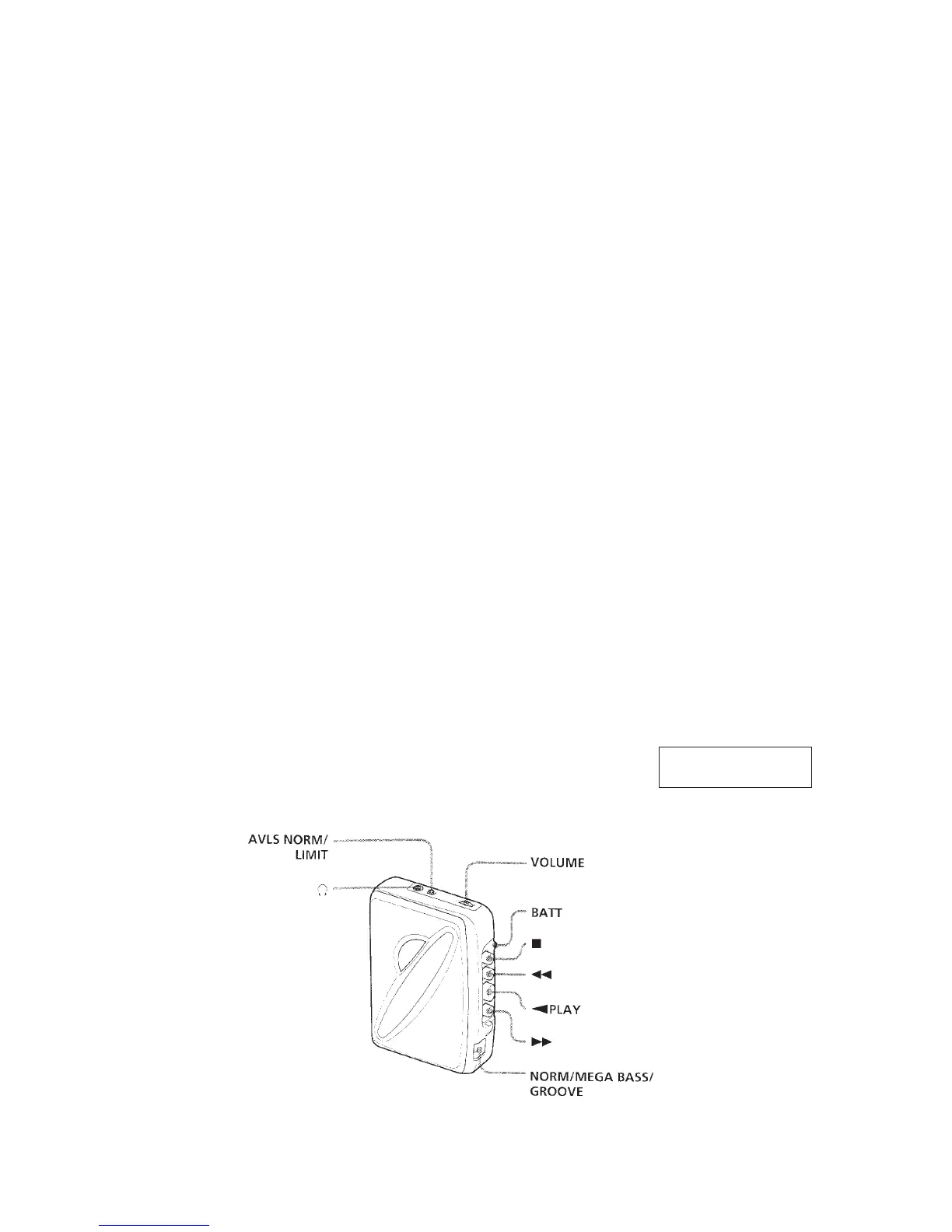
This section is extracted
from instruction manual.
 Loading...