Do you have a question about the Sony WM-FS473 and is the answer not in the manual?
Lists frequency ranges, power requirements, dimensions, mass, and included accessories for the device.
Guidance on maintaining waterproofing and handling specific components during repair.
Steps for removing the outer casing and the display board.
Steps for removing the cassette lid assembly and the chassis section.
Instructions for detaching the mechanism deck, main board, and belt.
Detailed procedures for mechanical torque measurements and electrical tuning adjustments.
Steps for AM/FM IF alignment, frequency coverage, and tracking adjustments.
Explanations of the function for each terminal of the ICs used in the device.
A high-level block diagram illustrating the functional blocks of the system.
Diagram showing the placement of components on the main printed wiring board.
Detailed circuit schematic for the main section of the device.
Detailed circuit schematic for the display section of the device.
Diagram showing component placement on the display board (Side A and B).
Visual breakdown of the cassette lid and main board sections with part references.
Detailed exploded view of the mechanism deck showing all parts and their references.
Lists electronic components categorized by display, headphone jack, and main boards.
Detailed part numbers and descriptions for semiconductors, resistors, and coils on the main board.
Lists variable resistors, filters, switches, and hardware items with their part numbers.
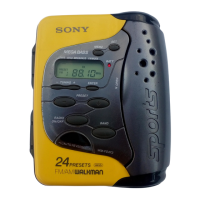
| Type | Cassette Player |
|---|---|
| Brand | Sony |
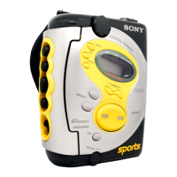
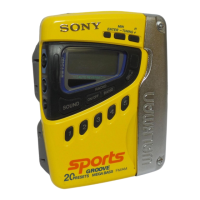
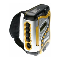
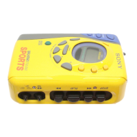
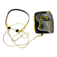
| Model | WM-FS473 |
| Tuner | FM/AM |
| Power Supply | 2 x AA Batteries |
| Play speed control | No |
| Noise Reduction | No |
| Radio | Yes |
| Recording | No |
| Auto reverse | No |
| Frequency Response | 40 Hz - 12, 000 Hz |
| Wow and Flutter | 0.15% |
| Power Source | 2 x AA batteries |