Do you have a question about the Sony WM-FS555 and is the answer not in the manual?
Steps to remove the chassis and headphone board.
Procedure for detaching and removing the main circuit board.
Detailed steps for disassembling the mechanism deck.
Instructions for replacing the belt, capstan/reel motor, and magnetic head.
Procedures for mechanical calibration and torque measurements.
Steps for electrical calibration, including tape speed.
Detailed pinout and function of the system control IC.
Overall system block diagram illustrating signal paths.
Layout of components and traces on the main circuit board.
First part of the main circuit schematic diagram.
Second part of the main circuit schematic diagram.
Block diagrams for key integrated circuits.
Exploded view and parts list for the cassette lid assembly.
Exploded view and parts list for the main cabinet.
Exploded view and parts list for the mechanism.
| Type | Cassette Player |
|---|---|
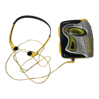
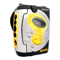
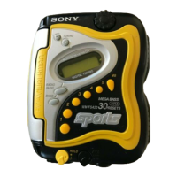
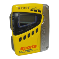
| Brand | Sony |
| Model | WM-FS555 |
| Tuner | FM/AM |
| Battery | 2 x AA |
| Mega Bass | Yes |
| Waterproof | No |
| Headphones Output | 3.5 mm |
| Power Supply | 2 x AA batteries or AC adapter |
| Playback Functions | Play, Stop, Fast Forward, Rewind |