2
WM-FS555/FS556
Specifications ........................................................................... 1
1. GENERAL ...................................................................... 2
2. DISASSEMBLY
2-1. Chassis, H/P Board ..................................................... 3
2-2. Main Board ................................................................. 3
2-3. Mechanism Deck ........................................................ 4
2-4. Belt, Capstan/reel Motor (M601),
Magnetic Head (Playback) (HP601) ........................... 4
3. ADJUSTMENTS
3-1. Mechanical Adjustments ............................................ 5
3-2. Electrical Adjustments ................................................ 5
4. DIAGRAMS
4-1. Explanation of IC Terminals....................................... 8
4-2. Block Diagrams .......................................................... 9
4-3. Printed Wiring Boards – Main Section – .................. 10
4-4. Schematic Diagram – Main Section (1/2)– ...............11
4-5. Schematic Diagram – Main Section (2/2)– .............. 12
4-6. IC Block Diagrams ................................................... 13
5. EXPLODED VIEWS
5-1. Cassette Lid Section ................................................. 15
5-2. Cabinet Section......................................................... 16
5-3. Mechanism Deck Section
(MF-WMFS555-114)............................ 17
6. ELECTRICAL PARTS LIST ................................... 18
Flexible Circuit Board Repairing
• Keep the temperature of the soldering iron around 270°C during
repairing.
• Do not touch the soldering iron on the same conductor of the
circuit board (within 3 times).
• Be careful not to apply force on the conductor when soldering or
unsoldering.
Notes on chip component replacement
• Never reuse a disconnected chip component.
• Notice that the minus side of a tantalum capacitor may be dam-
aged by heat.
TABLE OF CONTENTS
SECTION 1
GENERAL
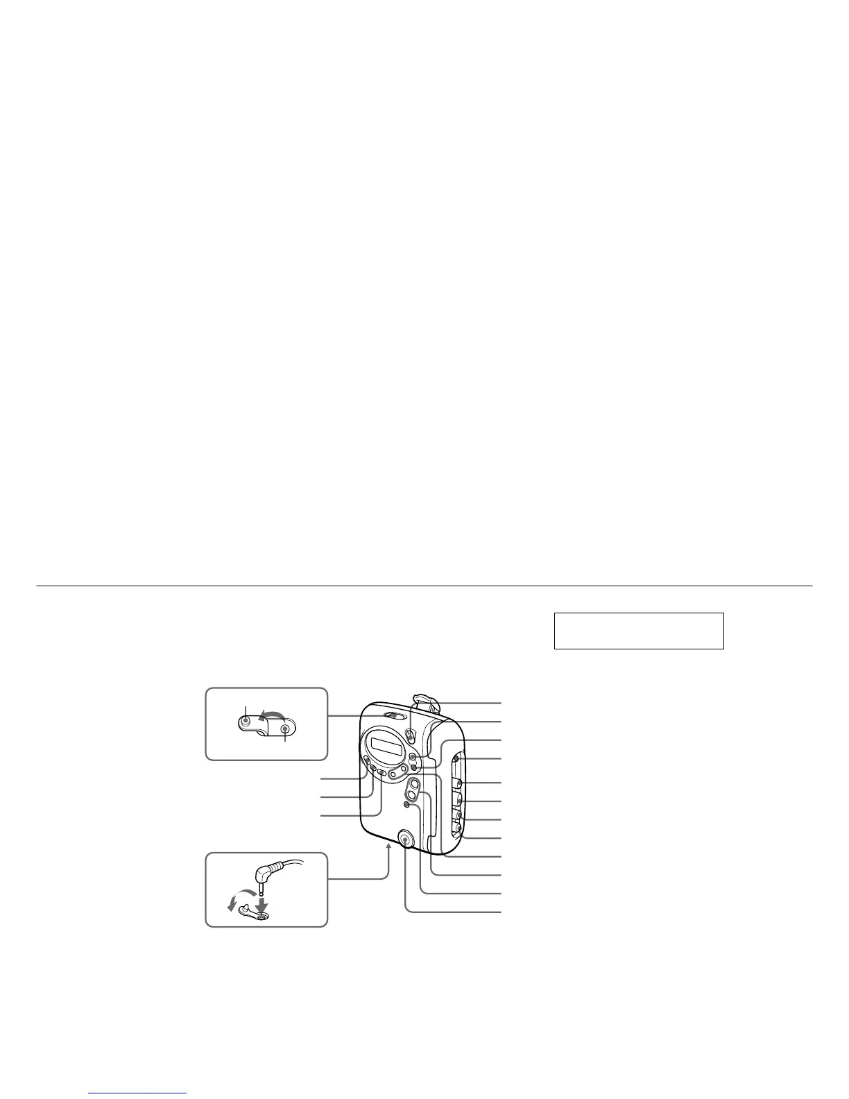
TV/WEATHER (US), FM (EXCEPT US)
HOLD
VOLUME*
TUNING+/–
x
Y
PRESET +/–
FM/AM (US), AM (EXCEPT US)
RADIO OFF
M
n**
m
MENU
SET
ENTER
Rubber cap
Air outlet
i
* There is a tactile dot beside VOLUME on the main unit to
show the direction to turn up the volume.
**
The button has a tactile dot.
This section is extracted from
instruction manual.

 Loading...