Do you have a question about the Sony WM-FS421 and is the answer not in the manual?
Guidance on detaching the main board and mechanism deck, involving solder removal and screws.
Specifies test tape, signal, and usage for tape speed adjustment procedures.
Procedure for adjusting the FM Voltage-Controlled Oscillator (VCO) using a frequency counter.
Steps for adjusting AM frequency coverage using a digital voltmeter.
Overall system block diagram illustrating signal paths and major component interconnections.
Detailed electronic schematic showing circuit connections, component values, and voltage points.
| Type | Cassette Player |
|---|---|
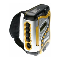
| Brand | Sony |
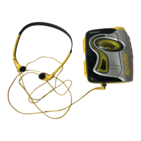
| Model | WM-FS421 |
| Tuner | FM/AM |
| Noise Reduction | Dolby B |
| Power Supply | 2 x AA batteries |
| Dimensions | 135 x 90 x 38 mm |
| Weight | 200 g |
| Signal-to-Noise Ratio | 50 dB |
| Play speed | 4.8 cm/s |
| Playback Speed | 1.875 ips |