2
TABLE OF CONTENTS
WM-FS421
1. GENERAL ·········································································· 2
2. SERVICE NOTE ······························································· 3
3. DISASSEMBLY
3-1. Main Assy······································································ 4
3-2. Chassis Sub Assy ··························································· 5
3-3. MAIN Board and Mechanism Deck······························ 5
3-4. Belt ················································································ 6
3-5. Head, Magnetic (HP701)··············································· 6
4. MECHANICAL ADJUSTMENT ·································· 7
5. ELECTRICAL ADJUSTMENT ···································· 7
6. DIAGRAMS
6-1. IC Block Diagrams ······················································ 10
6-2. Block Diagram ···························································· 11
6-3. Printed Wiring Board··················································· 12
6-4. Schematic Diagram ····················································· 13
6-5. IC Pin Function Description········································ 14
7. MEXPLODED VIEWS
7-1. Cabinet Assy Section··················································· 15
7-2. MAIN Board Section ·················································· 16
7-3. Mechanism Deck Section-1
(MF-WMFS421-114) ·················································· 17
7-4. Mechanism Deck Section-2
(MF-WMFS421-114) ·················································· 18
8. ELECTRICAL PPARTS LIST ···································· 19
SECTION 1
GENERAL
Notes on chip component replacement
• Never reuse a disconnected chip component.
• Notice that the minus side of a tantalum capacitor may be
damaged by heat.
Flexible Circuit Board Repairing
• Keep the temperature of soldering iron around 270˚C
during repairing.
• Do not touch the soldering iron on the same conductor of the
circuit board (within 3 times).
• Be careful not to apply force on the conductor when soldering
or unsoldering.
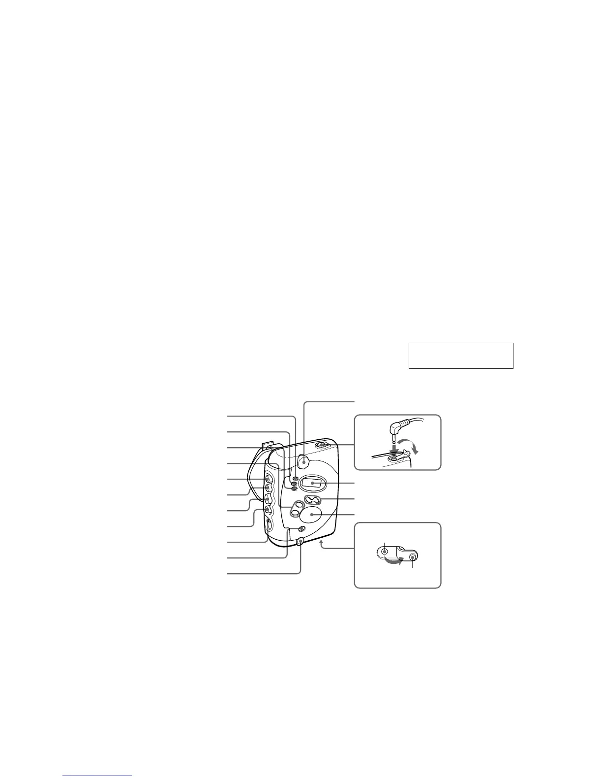
HOLD
OFF
N
M
FM, AM
PRESET +/–
m
x
Display
Afficheur
VOLUME
TUNING +, –
i
Y (FS422ST/FS421 only)
Y (FS422ST/FS421 uniquement)
MENU
SET
ENTER
Air outlet
Evacuation d’air
Rubber cap
Capuchon en
caoutchouc
This section is extracted
from instruction manual.
 Loading...