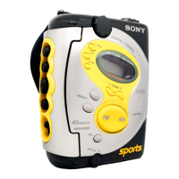
J301
(i)
Adjustment Location: Main board (See page 9)
0 dB = 1 µV
FM TRACKING ADJUSTMENT
Adjust for maximum reading on level meter.
L4 87.5 MHz
AM FREQUENCY COVERAGE ADJUSTMENT
Adjust for a 1.1V ± 0.1Vde reading on digital voltmeter
L7 530 kHz
AM TRACKING ADJUSTMENT
Adjust for maximum reading on level meter.
L3 620 kHz
CT1 1,400 kHz
• Repeat the procedures in each adjustment several times for the
maximum level meter indication.
• The frequency coverage and tracking adjustments should be
finally done by the trimmer capacitors.
AM IF ADJUSTMENT
Adjust for a maximum reading on level meter
RV2 1,000 kHz
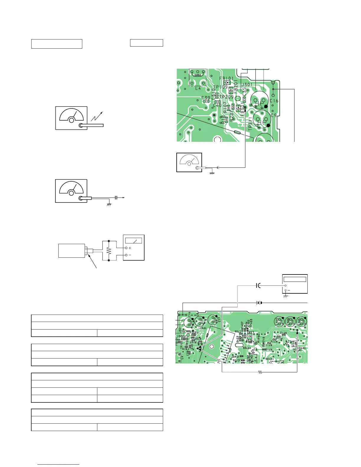
FM VCO Adjustment
Procedure:
1. Connect the resistor 10k between TP1 and TP (VCO).
2. Connect the frequency counter to TP1 (IC1 pin).
3. Set FUNCTION switch to FM.
4. Tune the set in 96MHz.
5. Adjust RV1 so that the reading on the frequency counter
becomes 76 kHz.
Specifications: 75 kHz-77 kHz
TP2
TP1
0.01F
FM RF SSG
[MAIN BOARD] (SIDE B)
Carrier frequency : 96MHz
Deviation : none
Output level : 562
µ
V(55dB)
TP2
(FM IN)
TP2
TP1
+
+
1
µ
F
[MAIN BOARD] (SIDE B)
frequency
counter
10k
Ω
TP1
TP
(VCO)
 Loading...