– 13 –
AM IF ADJUSTMENT
Adjust for a maximum reading on level meter
T2 450 kHz
AM VCO VOLTAGE ADJUSTMENT
Adjustment Part Frequency Display Reading on Digital Voltmeter
T1 531 kHz 1.5 ± 0.1 V
Confirmation 1602 kHz 8.5 ± 1 V
AM TRACKING ADJUSTMENT
Adjust for a maximum reading on level meter
L5 621 kHz
FM VCO VOLTAGE ADJUSTMENT
Adjustment Part Frequency Display Reading on Digital Voltmeter
L2 87.5 MHz 3.4 ± 0.1 V
Confirmation 108 MHz Less than 10 V
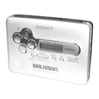
TUNER SECTION 0 dB=1 µV
[AM]
Setting:
function : RADIO
BAND button : AM
[FM]
Setting:
function : RADIO
BAND button : FM
• Repeat the procedures in each adjustment several times, and the
tracking adjustments should be finally done by the trimmer ca-
pacitors.
FM VCO Adjustment
Setting:
Procedure:
1. Connect the frequency counter to pin !™ of IC2 as shown the
figure below.
2. Tune the set to 98 MHz.
3. Adjust RV1 for 19 kHz reading on the frequency counter.
Specification: 18.95 kHz to 19.05 kHz
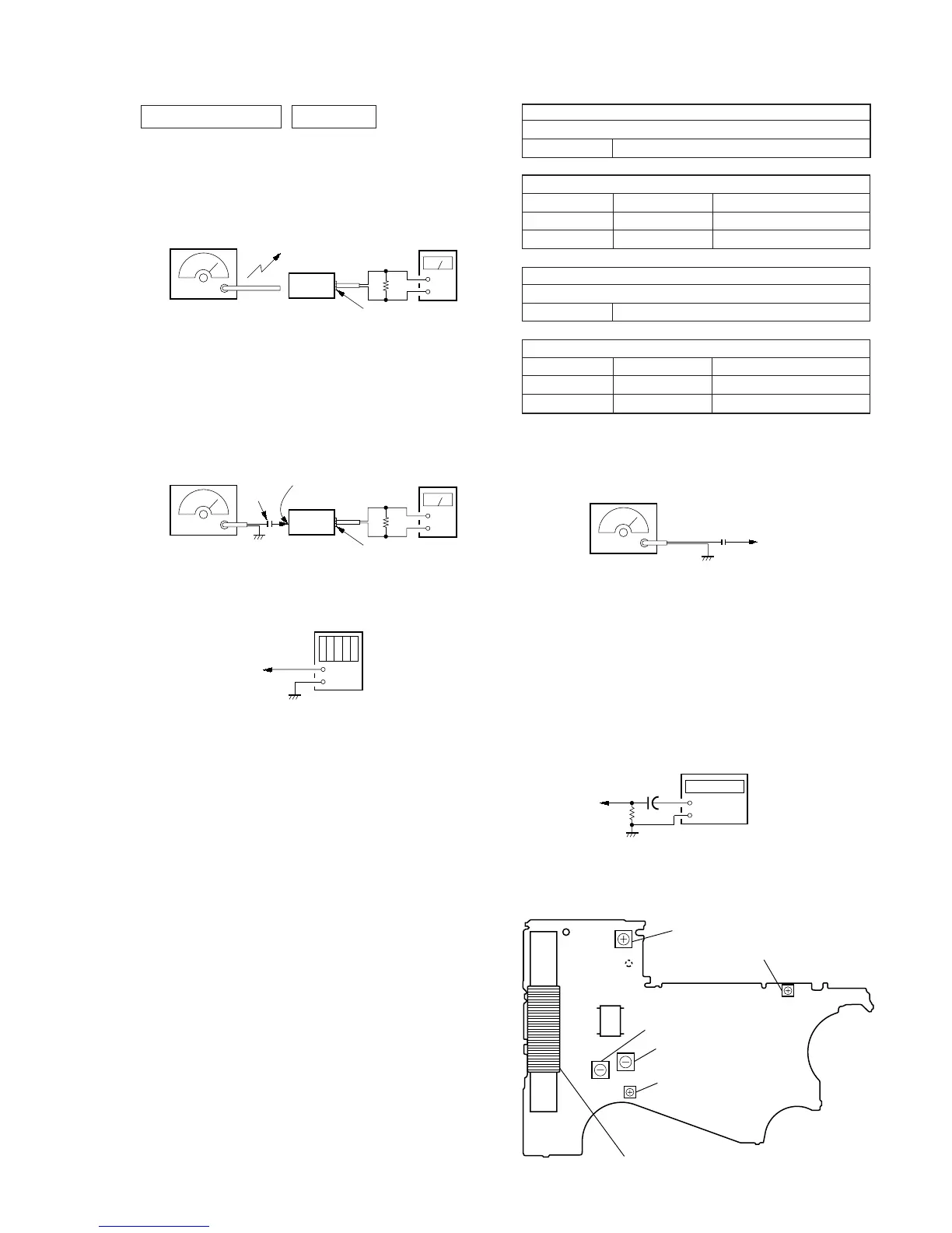
Adjustment Location:
0.001
µ
F
FM RF SSG
Carrier frequency : 98 MHz
Modulation : no modulation
Output level : 0.1 V (100 dB)
TP (FM IN)
+
–
digital voltmete
– MAIN Board (Side B) –
TP1
(FM IN)
IC2
1
12
T2 AM IF Adjustment
T1 AM VCO Voltage
Adjustment
L2 FM VCO Voltage Adjustment
RV1 FM VCO Adjustment
RV601 Tape Speed Adjustment
L5 AM Tracking Adjustment
TP2
(VT)
 Loading...