– 27 –
– 28 –
– 29 –
– 30 –
• Waveform
– MAIN BOARD –
1 IC3 &¢ (X OUT)
500 mV/DIV, 5 µs/DIV
1.3 Vp-p
75 kHz
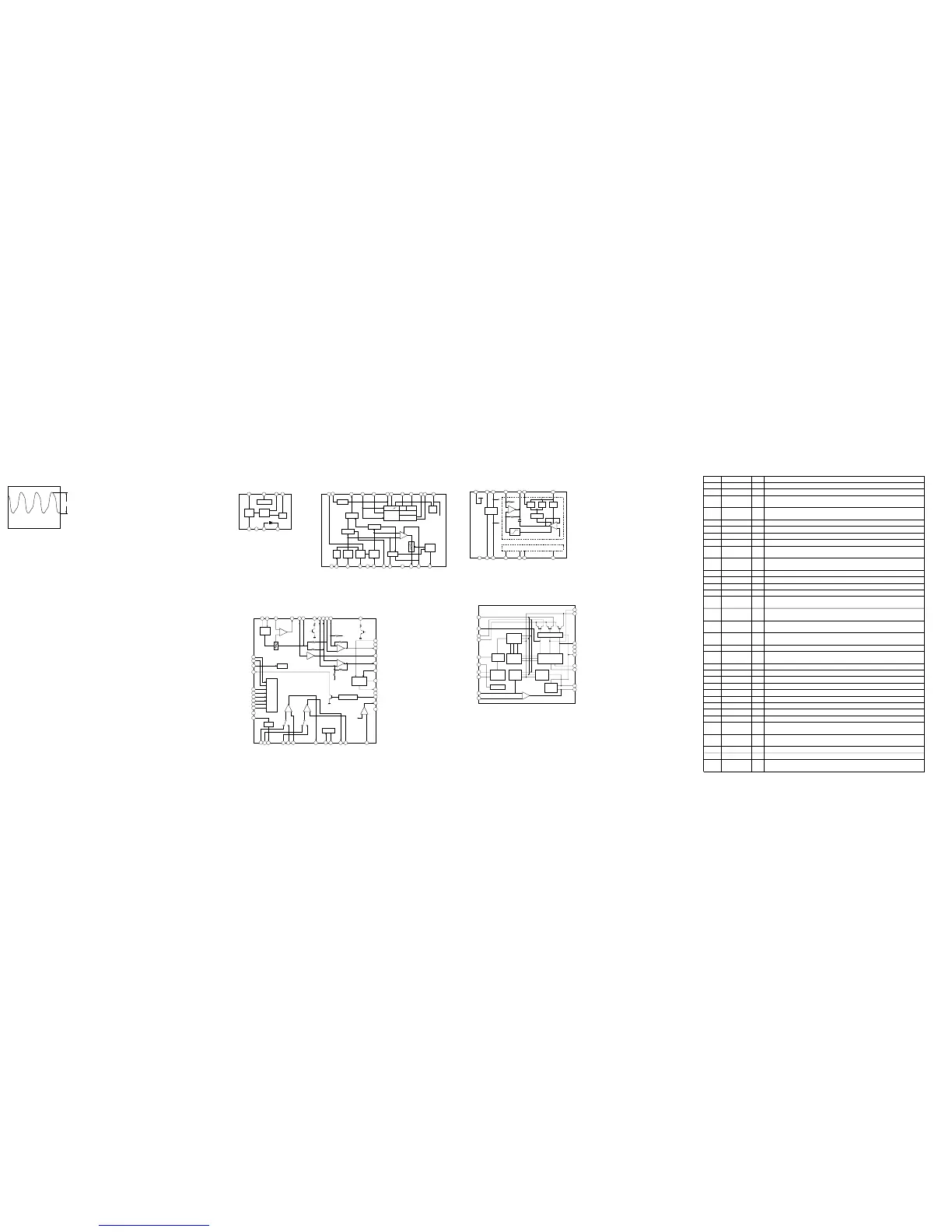
• IC Block Diagrams
IC1 TA7371AF-EL
IC301 TA2123AF (EL)
IC2 TA2022AFN-EL
RF OUT
VCC
MIX OUT
7 6
OSC
RF IN
GND
DFC
DIODE (C)
AFC
DIODE (A)
58
1 2 3 4
RF
AMP
MIX
AMP
OSC
REGULATOR
AM IF
PILOT
AM
FM
OSC
FM
IF AMP
FM DET
AF AMP
SWITCH
ST
IND
AM DET
AGC
STOP
PULSE
MIX
AM
IF AMP
VREF
OSC
FM IF IN
MIX OUT
VCC
AM IF IN
QUAD
AGC
GND
IF OUT
IF REQ
SP OUT
AM RF IN
PW SW
DET OUT
PILOT IN
MPX IN
LPF 2B
LPF 2A
VCO
LPF1
ROUT
LOUT
ST IND
1 7 8 9 10 11 126542 3
19202122
23
24 18
17
16 15 14 13
φ∠0°
VCO φ∠90°
DIVIDE
PRE
DECODE
PRE A
PRE B
MIX
PW B
PW A
PW C
BST
MT TC
BASE
RF IN
PW GND
OUT B
OUT C
OUT A
VCC
RF OUT
VREF OUT
BST NF
BST OUT
PW IN C
LPF
EQ A
PW NF A
PW IN A
PW IN B
PW NF B
3
IN A-R
5
PRE NF-A
6
PRE OUT A
7
MTL DRV A
8
MTL DRV B
9
PRE OUT B
10
PRE NF-B
11
AMS IN
12
IN B-R
4
IN B-F
2
IN A-F
1
21
20
19
18
17
GND
16
AMS DET
15
AMS MIX
14
AMS SW
13
22
23
24
38
C-AMP SW
37
PW SW
42
MT SW
41
F/R SW
44
BST SW
43
M/N SW
46
PRE GND
47
VREF IN
48
PRE SW
45
AMS OUT
40
BEEP
39
262728293031323334
DET
36
AGC IN
35
+
–
+
–
+
–
+
–
+
–
+
–
EQ B
25
RIPPLE
FILTER
AGC
DET
BEEP
VREF
SWITCH
COMPARATOR
MTL DRV
IC302 NJM2185AV-TE2
IC601 MM1279XVBE
891014 13 12
21 3
A-CH BLOCK
11
7654
G2
G1
V/I
WEIGHT
BIAS
CIRCUIT
+
–
+
–
GM
SUM
V+
SW
VEXT
OUTA
DCA
DETA
INA
GND
IREF
VREF
OUTB
DCB
DETB
INB
B-CH BLOCK: SAME AS A-CH.
V
1
PW
2
W
3
GND
4
OSC
5
DR
6
VREF
7
START
8
VSP
9
IN+
10
PV
20
U
19
PU
18
GND
17
VCC
16
FC
15
TC1
14
TC2
13
R1
12
OUT
11
MOTIVE
CONTROL
CIRCUIT
MOTIVE/
OSC
MOTIVE
LOGIC
SOFT SWITCH
PRE DRIVER
INVERTER
BIAS
REFERENCE
VOLTAGE
SPEED
CONTROL
CURRENT
CONTROL
OUTPUT
BIAS
+
–
6-5. IC PIN FUNCTION DESCRIPTION
• MAIN BOARD IC3 TC9327AF-606 (SYSTEM CONTROLLER, LIQUID CRYSTAL DISPLAY DRIVER)
Pin No. Pin Name I/O Description
1 to 4 COM1 to COM4 O
Common drive signal output to the liquid crystal display (LCD1)
5 to 22 S1 to S18 O
Segment drive signal output to the liquid crystal display (LCD1)
23
DOLBY VCC
CTL
O
Power on/off control signal output of the dolby NR amp (IC302)
“L”: power on, “H”: power off
24 SPEED CTL O
Motor speed control signal output to the capstan/reel motor driver IC (IC601)
“L”: normal speed, “H”: 1/2 speed
25 RADIO/MIC O Not used (open)
26 F/R CTL (REC) O Not used (open)
27 PRE CTL O Preamp on/off control signal output to the TA2123AF (IC301) “L”: tape play, “H”: radio on
28 MUTE CTL O Power on mute control signal output to the TA2123AF (IC301) “L”: mute on
29 F/R CTL (PLAY) O
Forward/reverse selection signal output to the TA2123AF (IC301)
“L”: reverse direction, “H”: forward direction
30 BAND FM/AM O
Power on/off control signal output of the FM circuit
“L”: power on (FM on), “H”: power off (AM or tape on)
31 R DATA OUT O Remote control data output to the remote commander
32 F TUME I “H” is input when amplifier on mode
33 R TUME I “H” is input when amplifier on mode
34 R DATA IN I Communication request input from the remote commander
35 HOLD SENS I
Hold status input of the HOLD switch (S2) “L”: hold off, “H”: hold on
“H” is input when key pressing at hold mode
36 OSC CTL O
Motor restart control signal output to the capstan/reel motor driver IC (IC601)
“L”: BL skip status, “H”: FF/REW motor rotation status
37 AMS IN I
Whether a music is present or not from TA2123AF (IC301) is detected at auto music sensor
“L”: music is present, “H”: music is not present
38 PHOTO CTL O
Control signal output to the capstan/reel motor rotation detect circuit
“L”: rotation detect circuit on
39 PHOTO IN I Rotation detect signal input of the capstan/reel motor (M601)
40 DDC1 CTL O
Power on/off control signal output of the DC/DC converter circuit
“L”: power off, “H”: power on
41 HOLD SW I Hold detect input from the HOLD switch (S2) “L”: hold on
42 BATT DET I Battery voltage detection signal input (A/D input)
43 KEY IN I Key input terminal (A/D input)
44 F/R SW I Tape direction switch (S1) input terminal (A/D input) “L”: forward position
45 A/D REF I Reference voltage (+1.6V) input for the A/D converter
46 CS O
Chip select signal output to the EEPROM (IC4)
47 M DATA I/O I/O
Two-way data bus with the EEPROM (IC4)
48 M CLOCK O
Serial clock signal output to the EEPROM (IC4)
49 BEEP O Beep sound signal output to the TA2123AF (IC301)
50 MOTOR CTL O
Motor start control signal output to the capstan/reel motor driver IC (IC601)
“L”: motor off, “H”: motor on
51 MOTOR DIR O
Motor direction control signal output to the capstan/reel motor driver IC (IC601)
“L”: clockwise, “H”: counterclockwise
52 TAPE I Cassette tape detect switch (S901-1) input terminal “L”: cassette detected, “H”: no cassette
53 REC CTL O Not used (open)
54 AVLS CTL O
AVLS (Automatic Volume Limiter System) on/off control signal output terminal
“L”: AVLS on “H”: AVLS off
 Loading...