– 31 –
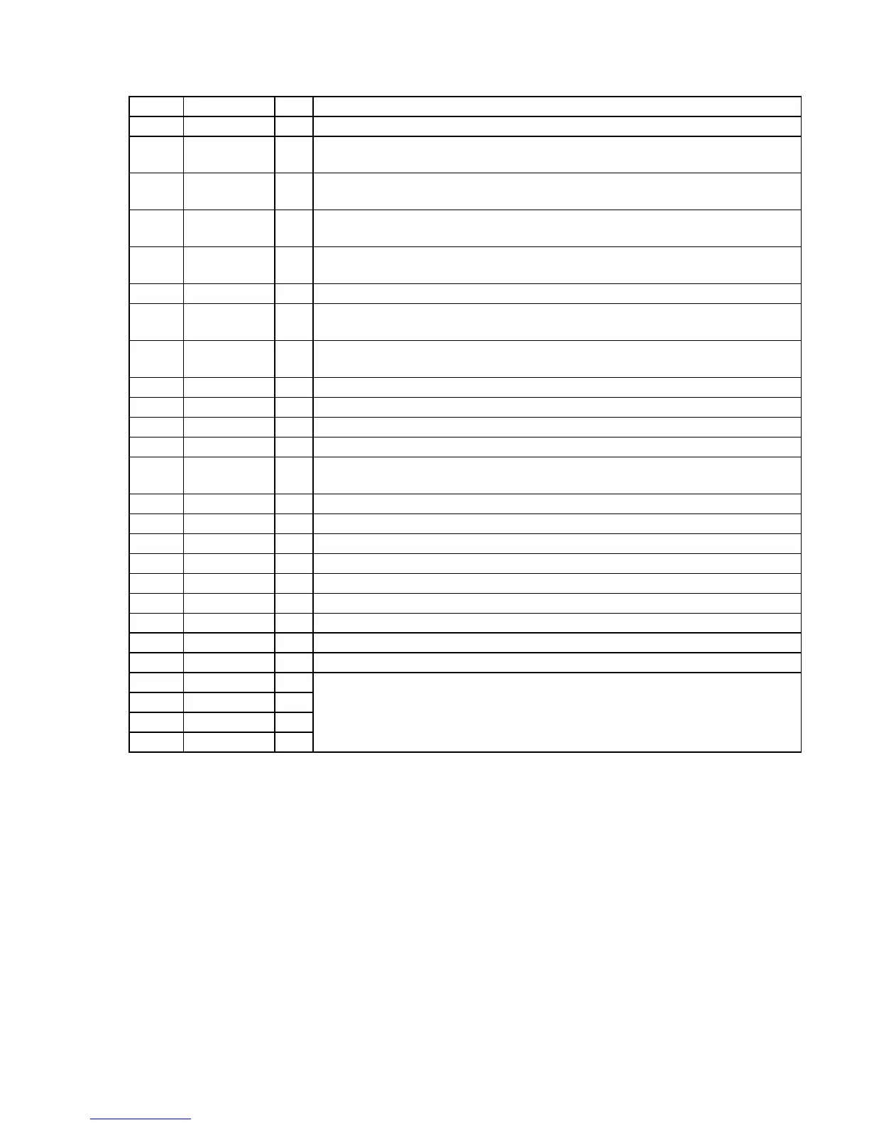
Pin No. Pin Name I/O Description
55 BOOST CTL O Bass boost control signal output to the TA2123AF (IC301) “L”: off, “H”: on
56 REVIVE CTL O
Emphasizing sound control signal output to the TA2123AF (IC301)
“L”: RV (revive), “H”: normal/MB (mega bass)/GRV (groove)
57 MB/GRV CTL O
Emphasizing sound control signal output to the TA2123AF (IC301)
“L”: normal/RV (revive)/GRV (groove), “H”: MB (mega bass)
58 AMP CTL O
Power on/off control signal output to the TA2123AF (IC301)
“L”: power off, “H”: power on
59 DOLBY CTL O
Dolby on/off control signal output to the dolby NR amp (IC302)
“L”: dolby NR on, “H”: dolby NR off
60 PM CTL O Plunger drive signal output terminal “L”: plunger on
61 DDC2 CTL O
Power on/off control signal output of the DC/DC converter circuit
“L”: power off, “H”: power on
62 RADIO CTL O
Power on/off control signal output of the FM and AM circuit
“L”: power on (FM or AM on), “H”: power off (tape on)
63 TEST I Test input terminal Normally: fixed at “L”
64 IF IN I Intermediate frequency detect signal input from the TA2022AFN (IC2)
65 LOCAL/DX O Local/DX select signal output terminal “L”: DX, “H”: local
66 DO O
PLL error signal output terminal
67 WAKE UP I
Input of acknowledge signal for the key entry
Acknowledge signal is input to accept function in the power off status On at input of “H”
68 MONO/ST O FM stereo/mono select signal output to the TA2022AFN (IC2) “L”: stereo, “H”: mono
69 GND — Ground terminal
70 FM IN I
FM VCO input terminal
71 AM IN I
AM (MW) VCO input terminal
72 VDD — Power supply terminal (+2.5V)
73
RESET I
System reset signal input terminal “L”: reset
74 XOUT O System clock output terminal (75 kHz)
75 XIN I System clock input terminal (75 kHz)
76 VXT — Terminal to which external capacitor is connected to stabilize crystal oscillator power supply
77 VLCD —
78 C1 —
79 C2 —
80 VEE —
Terminal for doubler circuit capacitor connection to develop liquid crystal display drive voltage
 Loading...