EasyManua.ls Logo

Sony WM-FX822 User Manual

Sony WM-FX822
28 pages
To Next Page IconTo Next Page
Page #1 background imageLoading...
Page #1 background image
— 1 —
Tourist Model
SERVICE MANUAL
WM-FX822
RADIO CASSETTE PLAYER
— Continued on next page —
SPECIFICATIONS
Model Name Using Similar Mechanism WM-EX510
Tape Transport Mechanism Type MT-WMEX510-112
Radio section
Frequency range
FM (stereo) : 76.0 - 90 MHz
AM (mono) : 531 - 1,710 kHz
TV (mono): 1 -12 ch
Tape player section and general
Frequency response
(a NR off)
20 - 18,000 Hz (EIAJ*)
Output
Headphones (2/REMOTE jack)
load impedance 8 - 300
Power output
4 mW + 4 mW (EIAJ, 16 )
DC1.5V
Power requirements
Rechargeable battery (NC-6WM)
One R6 (size AA) battery
Battery life (Approx. hours)
Dimensions
Approx. 108.5 x 78.6 x 23.0 mm (w/h/d)
incl. projecting parts and controls (EIAJ)
Mass
Main unit Approx. 145 g
For use Appox. 240 g (incl. Stereo
earphone with remote controller,
rechargeable battery NC-6WM, tape C-
60HF)
Design and specifications subject to change without notice.
Using AC power
Remove the rechargeable battery if inserted and attach the battery
case and connect the AC power adaptor (AC-E15L or AC-
E15HG) not supplied) to the DC IN 1.5V of the battery case and
to the wall outlet. Do not use any other AC power adaptor.
Dolby noise reduction manufactured under licence from Dolby
Laboratories Licensing Corporation.
“DOLBY” and the double-D symbol 8 are trademarks of Dolby
Laboratories Licensing Corporation.
*(EIAJ) Electric Industries Association of Japan
Polarity of
the plug
Rechargeable NC-6WM
fully charged
Playback 5
Radio/TV reception 7.5
Sony alkaline LR6 (WM)
Playback 16
Radio/TV reception 24
Sony R6P (SR)
Playback 3.5
Radio/TV reception 7
Ver 1.1 2002. 01
Sony Corporation
Personal Audio Company
Published by Sony Engineering Corporation
9-960-416-12
2002A1600-1
© 2002.1
w
w
w
.
x
i
a
o
y
u
1
6
3
.
c
o
m
Q
Q
3
7
6
3
1
5
1
5
0
9
9
2
8
9
4
2
9
8
T
E
L
1
3
9
4
2
2
9
6
5
1
3
9
9
2
8
9
4
2
9
8
0
5
1
5
1
3
6
7
3
Q
Q
TEL 13942296513 QQ 376315150 892498299
http://www.xiaoyu163.com
Question and Answer IconNeed help?

Do you have a question about the Sony WM-FX822 and is the answer not in the manual?

Sony WM-FX822 Specifications

General IconGeneral
BrandSony
ModelWM-FX822
CategoryCassette Player
LanguageEnglish

Summary

SPECIFICATIONS

Radio Section

Details on FM, AM, and TV frequency ranges and reception modes.

Tape Player and General

Frequency response, output power, and battery life for tape playback.

AC Power Usage

Instructions for using AC power adapter and battery case.

Service and Repair Notes

Chip Component Replacement Precautions

Guidelines for handling and replacing chip components safely.

Flexible Circuit Board Repairing

Procedures and precautions for repairing flexible circuit boards.

Safety-Related Component Warnings

Critical warnings for components vital to safe operation.

SECTION 1. GENERAL

Parts Identification: Tape Player

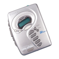
Visual identification of tape player and general section components.

Parts Identification: Radio

Visual identification of radio section components.

Supplied Accessories

List of items included with the product package.

SECTION 2. SERVICE NOTE

Service Mode Operation

Procedure to activate and configure the service mode for operation.

Preset State and Mode Configuration

Steps to set the player to a default state and operate in PLAY, FF, REW.

Rotation System Diagrams

Visual representations of the tape rotation system during PLAY, REW, and FF.

SECTION 3. DISASSEMBLY

Bracket and Cassette Holder Removal

Steps for removing the bracket and cassette holder components.

Audio Board Disassembly

Instructions for dismantling the audio board and its connections.

Tuner Board Disassembly

Steps for removing the tuner board from the unit.

SECTION 4. ADJUSTMENTS

Mechanical Adjustment Guidelines

Guidelines for cleaning, demagnetizing, and adjusting mechanical parts.

Tape Speed Calibration

Procedure for calibrating tape playback speed using a test tape.

Electrical Tuning Adjustments

Steps for adjusting FM IF, FM VCO, AM IF, AM Tuning Voltage, and AM Tracking.

SECTION 5. DIAGRAMS

Tuner Section Printed Wiring Board

Layout of components and connections on the tuner section's PWB.

Audio Section Printed Wiring Board

Layout of components and connections on the audio section's PWB.

Integrated Circuit Pin Functions

Detailed pin assignments and functions for key integrated circuits.

SECTION 6. EXPLODED VIEWS

Case and Tuner Board Exploded View

Illustrated breakdown of case and tuner board components with part numbers.

Audio Board Exploded View

Illustrated breakdown of audio board components with part numbers.

Mechanism Section Exploded View

Illustrated breakdown of the tape mechanism components with part numbers.

SECTION 7. ELECTRICAL PARTS LIST

Capacitors, Connectors, Diodes, ICs

List of capacitors, connectors, diodes, ferrite beads, and ICs with part numbers.

Transistors, Resistors, Switches

List of transistors, resistors, variable resistors, switches, and thermistors.

Tuner, Filter, and Accessory Parts

Detailed list of tuner components, filters, trimmers, and miscellaneous items.

REVISION HISTORY

Service Manual Update Log

Records of updates and changes made to the service manual over time.

Related product manuals