33
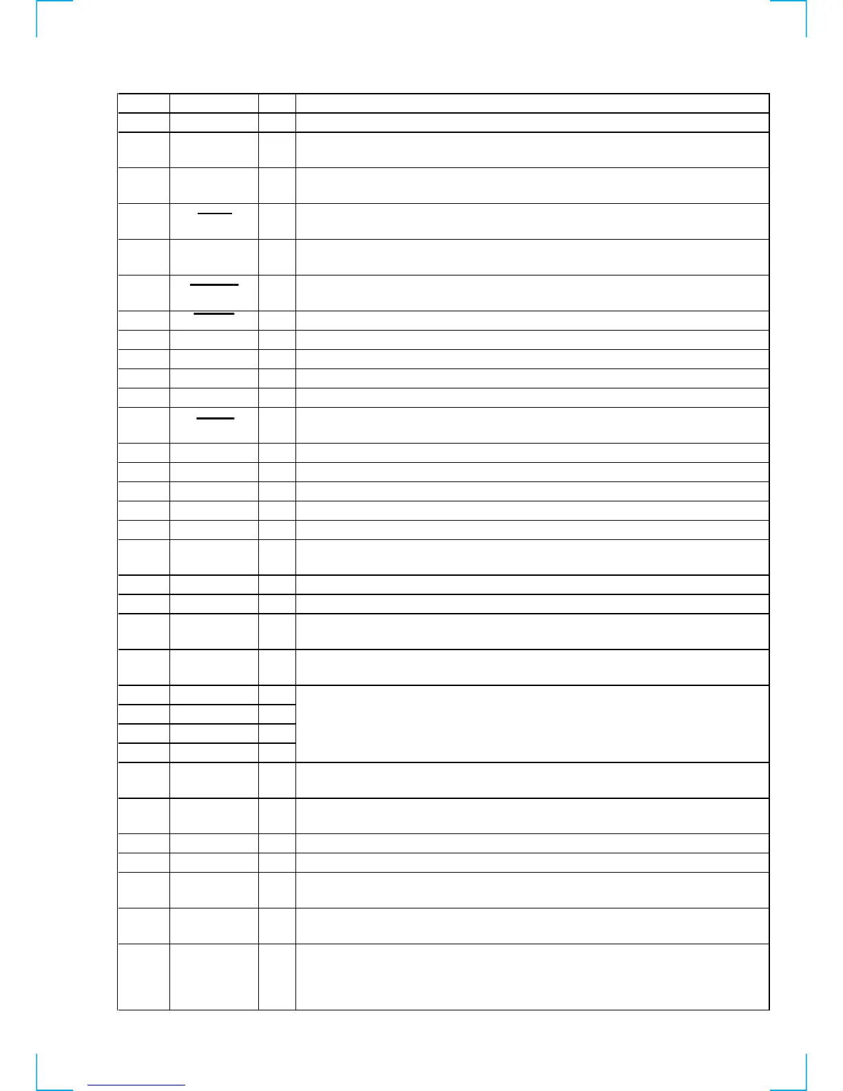
Pin No. Pin Name I/O Description
75 DAVN I
Data transmit completed detect signal input from the RDS decoder (IC51) “H” active
76 KEYACK
I
Input of acknowledge signal for the key entry Acknowledge signal is input to accept function
and eject keys in the power off status On at input of “H”
77 BU-IN
I
Battery detect signal input from the SONY bus interface (IC701) and battery detect circuit
“L” is input at low voltage IC701: Used for the XR-C33R only
78 ILL IN
I
Auto dimmer control illumination line detection signal input terminal
“L” is input at dimmer detection Fixed at “L” in this set
79
TEL-ATT I
Telephone muting signal input terminal At input of “H”, the signal is attenuated by –20 dB
Not used (open)
80 NOSESW I
Front panel block remove/attach detection signal input terminal
“L”: front panel is attached
81 ACC IN
I Accessory detect signal input terminal “L”: accessory on
82 to 85 NCO O
Not used (open)
86 HSTX I
Hardware standby input terminal “L”: hardware standby mode Reset signal input in this set
87 MD2 I
Setting terminal for the CPU operational mode (fixed at “L” in this set)
88, 89 MD1, MD0 I
Setting terminal for the CPU operational mode (fixed at “H” in this set)
90 RESET I
System reset signal input from the reset signal generator (IC652) and reset switch (S503)
“L”: reset “L” is input for several 100 msec after power on, then it changes to “H”
91 VSS —
Ground terminal
92 X0
I Main system clock input terminal (3.68 MHz)
93 X1
O Main system clock output terminal (3.68 MHz)
94 VCC —
Power supply terminal (+5V)
95 to 99 NCO O
Not used (open)
100 9K/10K I
AM frequency step (9 kHz or 10 kHz) selection signal input terminal
“L”: 9 kHz, “H”: 10 kHz Not used (open)
101 NCO O
Not used (open)
102 MTLIN I
Auto metal detection signal input terminal “L”: auto metal Fixed at “L” in this set
103 AMSIN I
Whether a music is present or not from CXA2509AQ (IC301) is detected at auto music sensor
“L”: music is present, “H”: music is not present
104 REEL I
Rotation detect signal input from supply reel sensor and take-up reel sensor on the deck
mechanism
105 POS0 I
106 POS1 I
107 POS2 I
108 POS3 I
109 LM-EJ O
Motor drive signal output to the loading/tape operation motor drive (IC361) “H” active
(For the eject direction and reverse side operation) *1
110 LM-LOD O
Motor drive signal output to the loading/tape operation motor drive (IC361) “H” active
(For the loading direction and forward side operation) *1
111 CM-ON O
Capstan/reel motor (M901) drive signal output terminal “H”: motor on
112 TAPEON O
Tape system power supply on/off control signal output terminal “H”: tape on
113 N-ROUT O
Forward/reverse direction control signal output to the CXA2509AQ (IC301)
“L”: forward direction, “H”: reverse direction
114 AMSON O
Tape auto music sensor control signal output to the CXA2509AQ (IC301)
“L” is output to lower the gain for audio level at FF/REW mode
115 MTLON I/O
Tape position (EJECT/FF/REW/
REV/FWD mode) detect input from
the tape operation switch on the deck
mechanism
POS0: “L”: EJECT mode, “H”: others mode
POS1: “L”: FF and FWD mode, “H”: others mode
POS2: “L”: REW mode, “H”: others mode
POS3: “L”: REV and EJECT mode, “H”: others mode
METAL control in/out terminal
At initial mode: auto/manual mode selection input of METAL function (manual at “L” input)
At manual mode: METAL on/off control signal output terminal (METAL on at “H” output)
At auto mode: input at MTLIN (pin <z/x)
 Loading...