EasyManua.ls Logo

Sony XR-C7200R Service Manual

Sony XR-C7200R
43 pages
To Next Page IconTo Next Page
Page #1 background imageLoading...
Page #1 background image
MICROFILM
SERVICE MANUAL
FM/MW/LW CASSETTE CAR STEREO
AEP Model
UK Model
Model Name Using Similar Mechanism NEW
Tape Transport Mechanism Type MG-25D-136
SPECIFICATIONS
XR-C7200R
For RM-X2S (Remote Commander),
please refer to RM-X2S/X3S Service
Manual (9-960-039-) previously issued.
Dolby noise reduction manufactured under license
from Dolby Laboratories Licensing Corporation.
“DOLBY” and the double-D symbol a are trade-
marks of Dolby Laboratories Licensing Corporation.

Other manuals for Sony XR-C7200R

Question and Answer IconNeed help?

Do you have a question about the Sony XR-C7200R and is the answer not in the manual?

Sony XR-C7200R Specifications

General IconGeneral
Display TypeLCD
Remote ControlYes
Channels4
WMA PlaybackNo
Radio TunerYes
DisplayYes
BluetoothNo
USB PortNo
Aux InputNo

Summary

Specifications Overview

General and Component Section Specifications

Details general specifications and specific details for cassette player, tuner, and amplifier sections.

General Information and Controls

Location of Controls

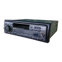
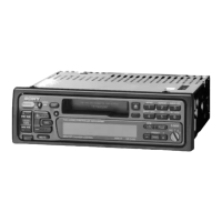
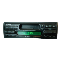
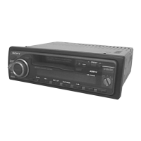
Identification and description of all buttons and controls on the unit.

Getting Started and Unit Setup

Unit Setup Procedures

Steps for resetting, detaching front panel, setting clock, and preparing commander.

Using the Car Stereo

Rotary Commander Operation and Sound Adjustment

Detailed instructions for operating the remote commander and adjusting audio settings.

Installation Guide

Vehicle Installation Instructions

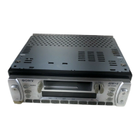
Step-by-step instructions for installing the car stereo unit into a vehicle.

System Connections

Component and Cable Connection Guide

Information on connecting various cables and components to the car stereo.

SECTION 2 DISASSEMBLY

Component Removal Procedures

Steps for disassembling cover, front panel, sub panel, mechanism deck, heat sink, and main board.

SECTION 3 ASSEMBLY OF MECHANISM DECK

Mechanism Deck Assembly Steps

Procedures for assembling housing, arm, lever, gear, and guide components.

SECTION 4 MECHANICAL ADJUSTMENTS

Torque and Tape Tension Measurement

Procedures for measuring and adjusting torque and tape tension.

SECTION 5 ELECTRICAL ADJUSTMENTS

Test Mode and Tape Deck Adjustment

Entering test mode and adjusting tape deck speed and Dolby level.

Tuner Section Adjustments

FM and MW Tuning Adjustments

Procedures for adjusting FM/MW tuner functions like scan levels, separation, and RDS S-meter.

Adjustment Component Locations

Diagrams of Adjustment Points

Diagrams showing the physical locations of adjustment points on the circuit boards.

SECTION 6 DIAGRAMS

IC Pin Function Descriptions

Detailed pinout descriptions for the main integrated circuits.

Printed Wiring Board - Main Section

Main Board Layout and Components

Layout and component placement for the main printed circuit board.

Schematic Diagram - Main Section

Main Board Circuit Schematic

Electrical schematic for the main circuit board.

Panel Section Diagrams

Printed Wiring and Schematic Diagrams

Layout and schematic details for the panel circuit boards.

Signal Waveforms

Main and Panel Section Waveforms

Visual representations of key signal waveforms at specific test points.

IC Block Diagrams

Main Board IC Block Diagrams

Functional block diagrams for integrated circuits on the main board.

SECTION 7 EXPLODED VIEWS

Exploded Views of Major Assemblies

Visual guides showing the breakdown of chassis, front panel, and mechanism deck assemblies.

SECTION 8 ELECTRICAL PARTS LIST

Component Listings

Comprehensive list of all electrical components, their part numbers, and descriptions.

Related product manuals