– 21 –
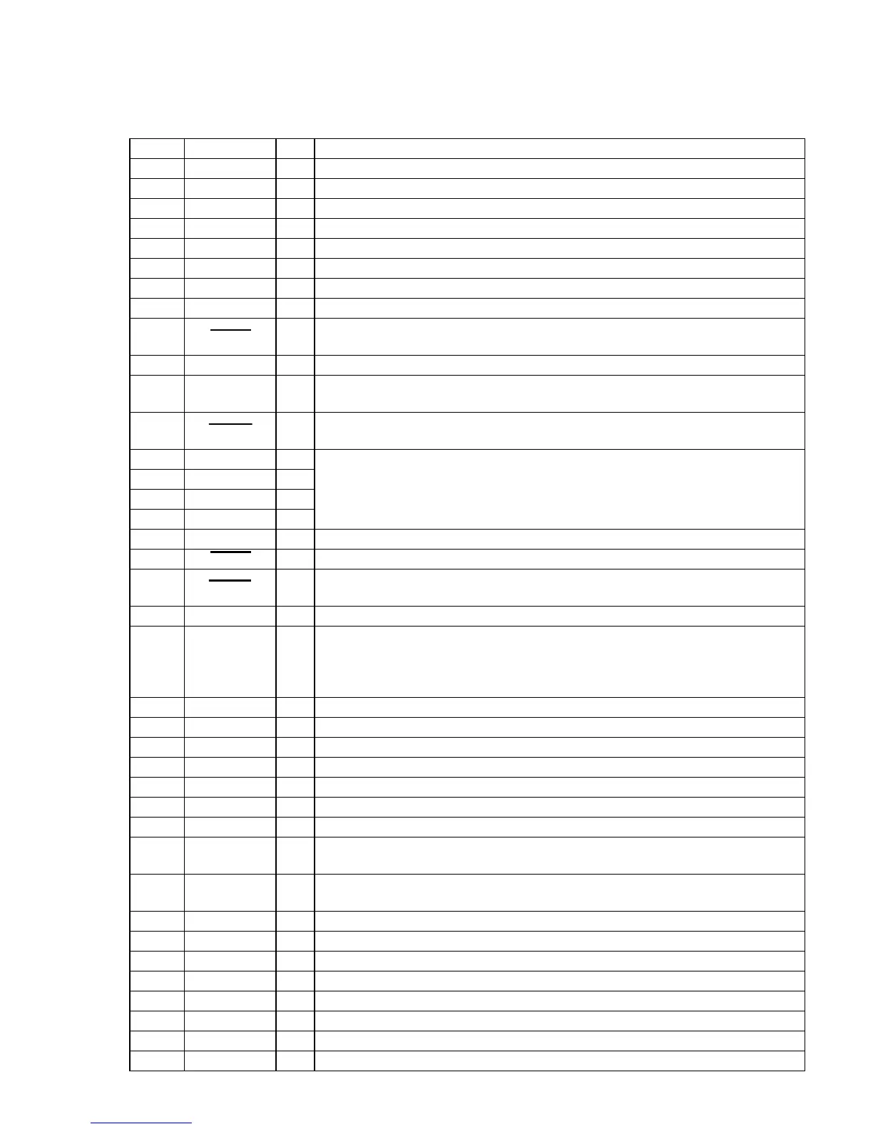
6-1. IC PIN FUNCTION DESCRIPTION
SECTION 6
DIAGRAMS
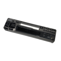
• MAIN BOARD IC101 MN1884820Y5F1 (TUNER/TAPE DECK SYSTEM CONTROLLER)
Pin No. Pin Name I/O Function
1 to 6 NCO O Not used (open)
7 VDD — Power supply terminal (+5V)
8 X1 I Main system clock input terminal (8 MHz)
9 X2 O Main system clock output terminal (8 MHz)
10 GND — Ground terminal
11 XI I Sub system clock input terminal Not used (fixed at “L”)
12 NCO O Not used (open)
13 XO O Sub system clock output terminal Not used (open)
14 RESET I
System reset signal input from the system controller (IC501), reset signal generator (IC551) and
reset switch (S551) “L” is input for several 100 msec after power on, then it changes to “H”
15 RDSCKI I Serial data reading clock signal input from the RDS decoder (IC150)
16 BU IN I
Battery detect signal input from the SONY bus interface (IC571) and battery check circuit
“H”: battery on
17 BUSON I
Bus on/off control signal input from the system controller (IC501) (for SONY bus)
“L”: bus on
18 POS3 I
19 POS2 I
20 POS1 I
21 POS0 I
22 NIL I Not used (fixed at “L”)
23 MTLIN I Auto METAL detect signal input from the METAL detect switch on the mechanism block
24 AMSIN I
Whether a music is present or not from CXA2510AQ (IC210) is detected at auto music sensor
“L”: music is present, “H”: music is not present
25 TAPIN I Not used (fixed at “L”)
26 DOLON I/O
27 NCO O Not used (open)
28 TAPMUT O Tape muting on/off control signal output to the CXA2510AQ (IC210) “H”: tape muting on
29 MTLON O METAL on/off control signal output to the CXA2510AQ (IC210) “H”: METAL on
30 RDSSI I Serial data input from the RDS decoder (IC150)
31 NIL I Not used (fixed at “L”)
32 CM-ON O Capstan/reel motor (M901) drive signal output terminal “H”: motor on
33 TAP-ON O Tape system power supply on/off control signal output terminal “H”: tape on
34 LMEJ O
Loading/tape operation motor control signal output to the LB1638M (IC201)
(For the eject direction and reverse side operation) *1
35 LMLOD O
Loading/tape operation motor control signal output to the LB1638M (IC201)
(For the loading direction and forward side operation) *1
36 NIL I Not used (fixed at “L”)
37 REEL I Reel table rotation detect signal input from the take-up and supply reel sensor
38 PLL-DI I PLL serial data input from the FM/AM PLL (IC10)
39 PLL-DO O PLL serial data output to the FM/AM PLL (IC10)
40 PLL-CLK O PLL serial data transfer clock signal output to the FM/AM PLL (IC10)
41 CE O PLL serial chip enable output to the FM/AM PLL (IC10)
42 RQ O Communication request signal output to the SONY bus interface (IC571)
43 LINK-OFF O Unilink on/off control signal output (for SONY bus) “L”: link on
Tape position detect input from the tape operation switch on the mechanism block
Dolby control in/out terminal
At initial mode: valid/invalid selection input of dolby function (“L” input: valid)
At normal mode: dolby on/off control signal output to the CXA2510AQ (IC210)
“H”: dolby on
 Loading...