The Sophos XG 105(w)/115(w)/125(w)/135(w) Rev. 3 and XG 106(w) Rev.1 are hardware appliances designed for network security, suitable for commercial, industrial, and residential environments. These models can operate as standalone appliances and belong to appliance group B. They comply with various international standards including CB, CE, FCC Class B, ISED, VCCI, RCM, UL, CCC, and BIS. To maintain CE and FCC compliance, only CE and FCC compliant parts and proper cabling techniques must be used.
Function Description:
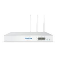
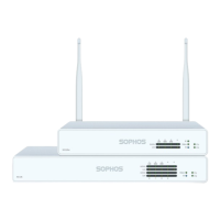
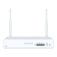
These appliances serve as network security devices, offering functionalities typically found in firewalls and unified threat management (UTM) systems. They are designed to be installed and configured to protect networks. The "w" in the model names indicates Wi-Fi capability, with specific models like XG 125w and XG 135w featuring external antennas for wireless connectivity.
Important Technical Specifications:
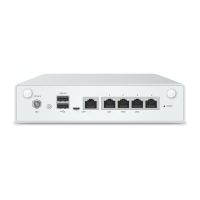
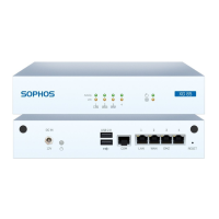
Physical Connections and Indicators:
The devices feature a range of ports and LED indicators for status monitoring and connectivity.
LED Status Indicators:
-
Storage Status (Blue LED): Flashing indicates SSD drive access.
-
Storage Status (Green LED): Constantly on indicates normal operation. Flashing indicates device booting up or shutting down.
-
Storage Status (Red LED): Constantly on indicates SSD or boot failure. Flashing indicates a general error (requires support contact).
-
Wifi (Green LED): On indicates Wi-Fi is active. Off indicates Wi-Fi is inactive.
-
Power 1/Power 2 (Green LED): Constantly on indicates the respective power adapter is in normal operation.
-
Power 1/Power 2 (Red LED): Constantly on indicates the respective power adapter failed or is disconnected.
-
RJ45 Ethernet Connector LEDs (ACT/LNK - Left LED):
- Green, Constantly on: Ethernet port is receiving power, good connection to the Ethernet port and hub.
- Flashing: Adapter is sending or receiving network data; flash frequency varies with traffic.
- Off: Adapter and switch not receiving power, no connection between network ends, or network drivers not loaded/functioning.
-
RJ45 Ethernet Connector LEDs (Speed - Right LED):
- Amber, On: Ethernet port operating at 1,000 Mbps.
- Green, On: Ethernet port operating at 100 Mbps.
- Off: Ethernet port operating at 10 Mbps.
-
SFP Connector LEDs (ACT/LNK - Left LED):
- Green, Constantly on: SFP connector is receiving power, good connection between the SFP connector and hub.
- Flashing: Adapter is sending or receiving network data; flash frequency varies with traffic.
- Off: Adapter and switch not receiving power, no connection between network ends, or network drivers not loaded/functioning.
-
SFP Connector LEDs (Speed - Right LED):
- Amber, On: SFP connector operating at 1,000 Mbps.
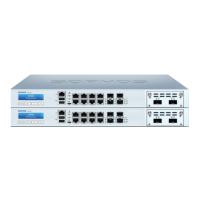
SFP Port Specifications:
The SFP port supports various Mini-GBIC module types depending on the network requirements.
- 1000 Base-T: IEEE 802.3 - 1 Gbit/s via Ethernet cable (Category 5), max distance 100 meters.
- 1000 Base-SX: IEEE 802.3 - 1 Gbit/s via multi-mode fiberglass cables (MMF), distance 200 m to 550 m.
- 1000 Base-LX: IEEE 802.3 - 1 Gbit/s via single-mode fiberglass, distance approximately 10 km.
- Laser Safety: SFP GBIC fiber modules use Class 1 Laser equipment. Users should never look directly at a transmit port when powered on. Only UL approved Laser Class I Transceivers, rated 3.3Vdc, max. 1W, should be used.
- Shared Port (XG 105/106/115): On these models, the SFP port is shared with RJ45 Ethernet Port 4 and takes precedence if cables are connected to both simultaneously.
Expansion Modules (XG 125(w)/135(w) only):
These models support optional 3G/4G or Wireless modules (on XG 135w only). These modules are region-dependent (Americas/EMEA vs. APAC).
-
4G LTE (Cat-6):
- Americas/EMEA Frequency Bands: B1, B2, B3, B4, B5, B7, B12, B13, B20, B25, B26, B29, B30, B41.
- APAC Frequency Bands: B1, B3, B5, B7, B8, B18, B19, B21, B28, B38, B39, B40, B41.
- Peak Download Rate: 300 Mbps.
- Peak Upload Rate: 50 Mbps.
-
3G (WCDMA):
- Americas/EMEA Frequency Bands: B1, B2, B3, B4, B5, B8.
- APAC Frequency Bands: B1, B5, B6, B8, B9, B19 (WCDMA) and B39 (TD-SCDMA).
- Peak Download Rate: 300 Mbps.
- Peak Upload Rate: 50 Mbps.
-
Location Services: GPS, Galileo, Glonass, Beidou are supported across all regions for these modules.
Serial Console Settings:
- Bits per second: 38,400
- Data bits: 8
- Parity: N (none)
- Stop bits: 1
Access via the serial console is activated by default on ttyS1. An RJ45 to DB9 adapter cable or the provided USB cable can be used for connection.
Usage Features:
Installation and Configuration:
- Initial Setup: The hardware appliance can be connected and configured using the Hardware Quick Start Guide. Initial software setup can be done via a WebAdmin Quick Start Guide wizard or manually using the Sophos XG Firewall Administrator Guide.
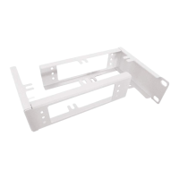
- Mounting: Appliances can be placed on a stable horizontal surface, mounted to a rack, or hung on a wall using an optional rackmount kit.
- Rack Precautions: Ensure leveling jacks are fully extended, stabilizers are attached for single rack installations, and racks are coupled for multiple installations. Always ensure rack stability before extending components. Extend only one component at a time to prevent instability.
- General Server Precautions: Review electrical and safety precautions. Determine component placement before installing rails. Install heaviest components at the bottom of the rack first. Allow hot-plug drives and power supply modules to cool before touching. Keep the rack's front door and panels closed to maintain proper cooling.
- Rack Mounting Considerations:
- Ambient Operating Temperature: Ensure the rack environment's ambient temperature is compatible with the manufacturer's maximum rated temperature, as it may be higher than the room temperature.
- Reduced Airflow: Mount equipment to allow sufficient airflow for cooling.
- Mechanical Loading: Mount equipment to prevent hazardous conditions from uneven loading.
- Circuit Overloading: Consider the power supply circuitry and potential overloading effects on overcurrent protection and wiring. Use equipment nameplate ratings for assessment.
- Reliable Ground: Maintain reliable grounding at all times, ensuring the rack itself is grounded. Pay attention to power supply connections, including power strips.
SFP Module Installation/Removal:
- Installation: Carefully insert the SFP module into the port until it engages. The interface becomes immediately ready for use. Refer to the SFP module's operation manual.
- Removal:
- Remove any fiberglass cable from the module.
- Carefully remove the module from the port.
SFP modules may have different release mechanisms (plastic tab, wire bail, or plastic collar); refer to the SFP module's operation manual.
Expansion Module Installation:
- For XG 125(w)/135(w) models, optional 3G/4G or Wireless modules can be installed in the expansion bay. Refer to the mounting instructions shipped with each module.
Maintenance Features:
Battery Replacement:
- Caution: Risk of explosion if the battery is replaced with an incorrect type. Dispose of used batteries according to instructions.
Documentation:
- User manuals and additional documentation are available on the Sophos support webpage: sophos.com/support.
Safety Symbols:
- An exclamation mark symbol indicates "Caution and Important Note." Failure to observe these notes can lead to danger to life and the environment, appliance damage, loss of appliance functions, and Sophos not being liable for damages.