#EMG2000 MAGNUM™ DC LED Lightbar
EMG2000-DC 10.15
10
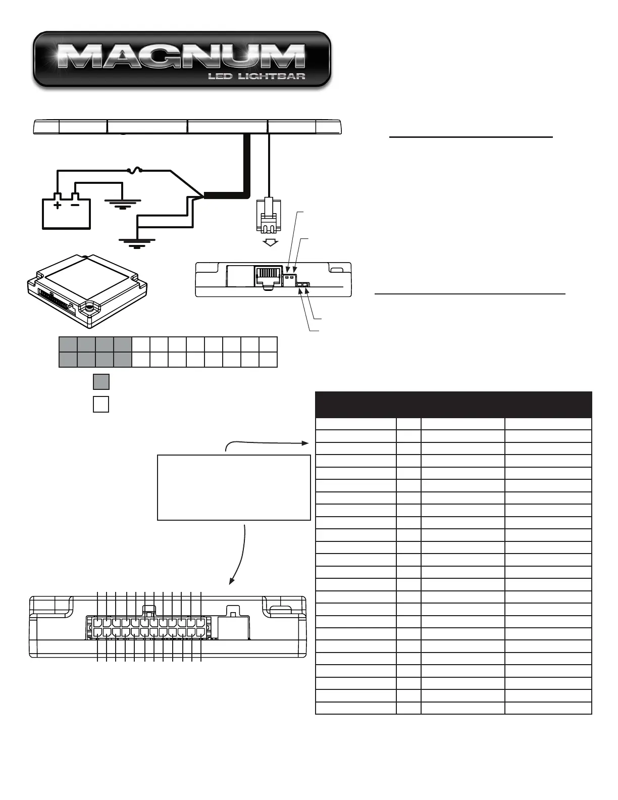
DRAIN WIRE
BLACK 12 GA.
GROUND
40Amp FUSE
(Customer Supplied)
GROUND
RED
12
G
A.
RED LIGHT
No Input Flashes every 5 seconds
Input Activated Steady On
Added Input Brief Flash
GREEN LIGHT
Command Rec'd Steady On Has good connection
(See Below)
· Up = Active High
· Down = Active Low
· When the switch is in the up position inputs
connected to that switch are active high. To
activate an active high input, apply 12Vdc.
· When the switch is in the down position Inputs
connected to that switch are active low. To
activate the active low, apply ground (negative).
CABLE RJ-45
Switch #1
Switch #2
Red LED
Green LED
Wire Color
(Major Color/ Stripe)
Pln#
Standard Functions
(4 Wire Arrow Control)
Discrete Functions
(8 Wire Arrow Control)
Light Green/ White 24 Left Turn Signal* Discrete Output #4*
Red/ Black 23 Right Turn Signal* Discrete Output #3*
Orange/ White 22 Rear Inboard 3 Discrete Output #2*
Yellow/ White 21 Rear Inboard 2 Discrete Output #1* (L)*
Brown 20 Front Take down Front Take down
Red/ White 19 Alley Flash Alley Flash
Pink 18 Alley Driver Alley Driver
Red 17 Alley Passenger Alley Passenger
Orange 16 Front Inboard 3 Front Inboard 3
Yellow 15 Front Inboard 2 Front Inboard 2
Green 14 Front Inboard 1 Front Inboard 1
Blue 13 Front Corners Front Corners
Pink/ White 12 Arrow, Left* Discrete Output #8 (R)*
Purple/ White 11 Arrow, Center* Discrete Output #7*
Gray/ White 10 Arrow, Right* Discrete Output #6*
Black/ White 9 Arrow, Warning Discrete Output #5*
White 8 Pattern Select* Pattern Select*
Purple 7 Low Power Low Power
Brown/ White 6 Front Take down Flash Front Take down Flash
Light Green 5 Auxilary* Auxilary*
Black 4 Cruise Lights* Cruise Lights*
Gray 3 Mode Select* Mode Select*
Green/ White 2 Rear Inboard 1 Rear Inboard 1
Blue/ White 1 Rear Corners Rear Corners
24 23 22 21 20 19 18 17 16 15 14 13
12 11 10 9 8 7 6 5 4 3 2 1
Connector Pinning Chart
Controlled by Active Low Switch #2
Controlled by Active Low Switch #1
PIN#24 - Light Green/ White
PIN#23 - Red Black
PIN#22 - Orange/ White
PIN#21 - Yellow/ White
PIN#20 - Brown
PIN#19 - Red/ White
PIN#18 - Pink
PIN#17 - Red
PIN#16 - Orange
PIN#15 - Yellow
PIN#14 - Green
PIN#13 - Blue
Pink/ White - PIN#12
Purple/ White - PIN#11
Gray/ White - PIN#10
Black/ White - PIN#9
White - PIN#8
Purple - PIN#7
Brown/ White - PIN#6
Light Green - PIN#5
Black - PIN#4
Gray - PIN#3
Green White - PIN#2
Blue/ White - PIN#1
Note - Reference Switch table for explanation of what inputs are affected by
Active Low Switches.
Functional Inputs
Functional Inputs connect to your control
head or switching unit. Applying +12Vdc
to any functional Input will activate it's
function (default-active high).
POWERCABLE
WITH BREAKOUT BOX
 Loading...