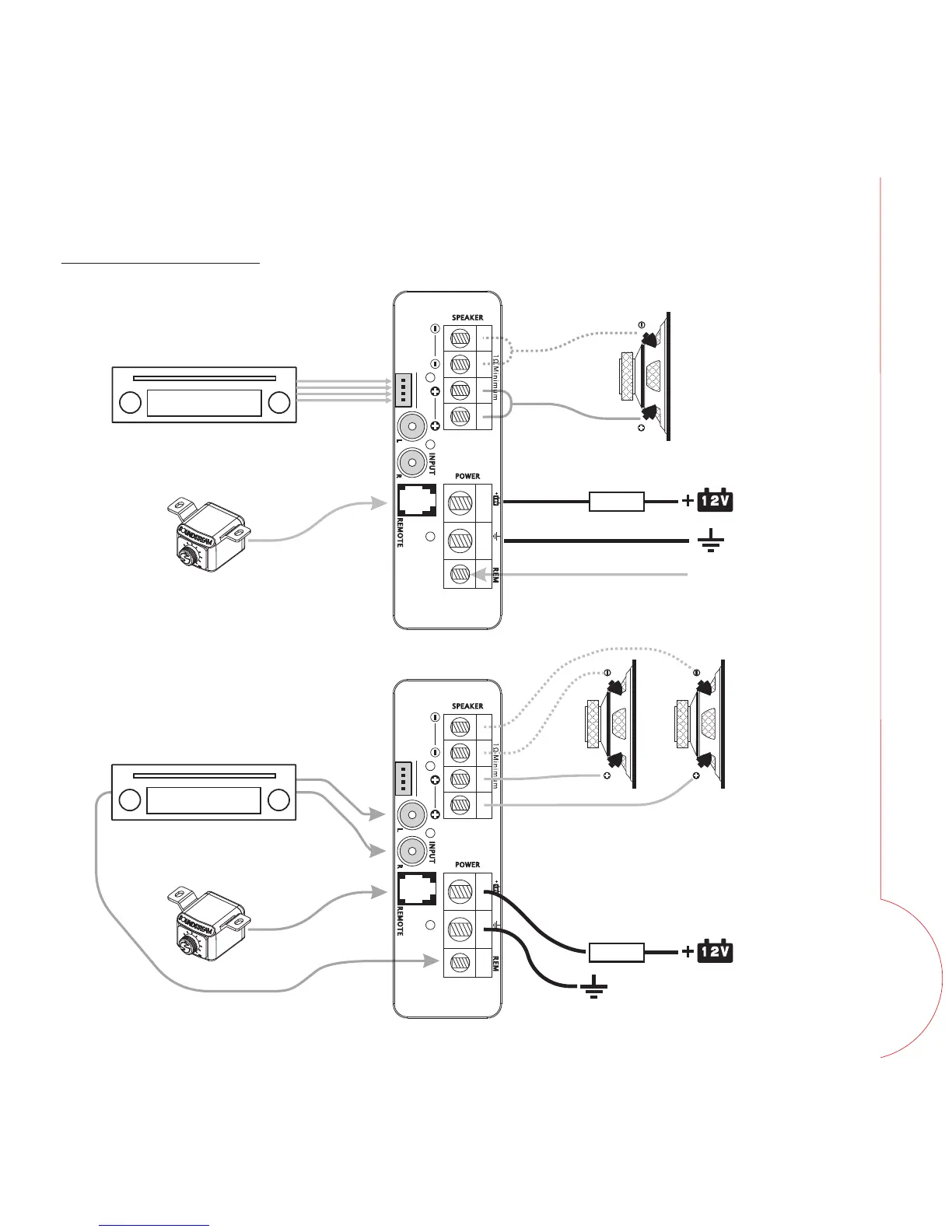
Fig 5. Mono amplifier wiring
WIRING DIAGRAM
(High level input mode)
Fig 6. Mono amplifier wiring
(multi woofers)
FUSE
Source Unit / Original Amplifier
ON/OFF control signal
FUSE
Source Unit
R
CA sig
nal
REMOTE signal
Speaker signal
HI G H- INP U T
L+ L - R+ R -
HI G H- INP U T
L+ L - R+ R -
*Equivalent parallel woofer load cannot be
less than the minimum load rating. The 2
negative terminals are paralleled inside the
amplifiers, as are the 2 positive terminals.
These are monoblock amplifiers, not multi-
channel amplifiers.
WIRING
 Loading...