good rule of thumb is that any head unit producing 5 or more true watts a channel is BTL.
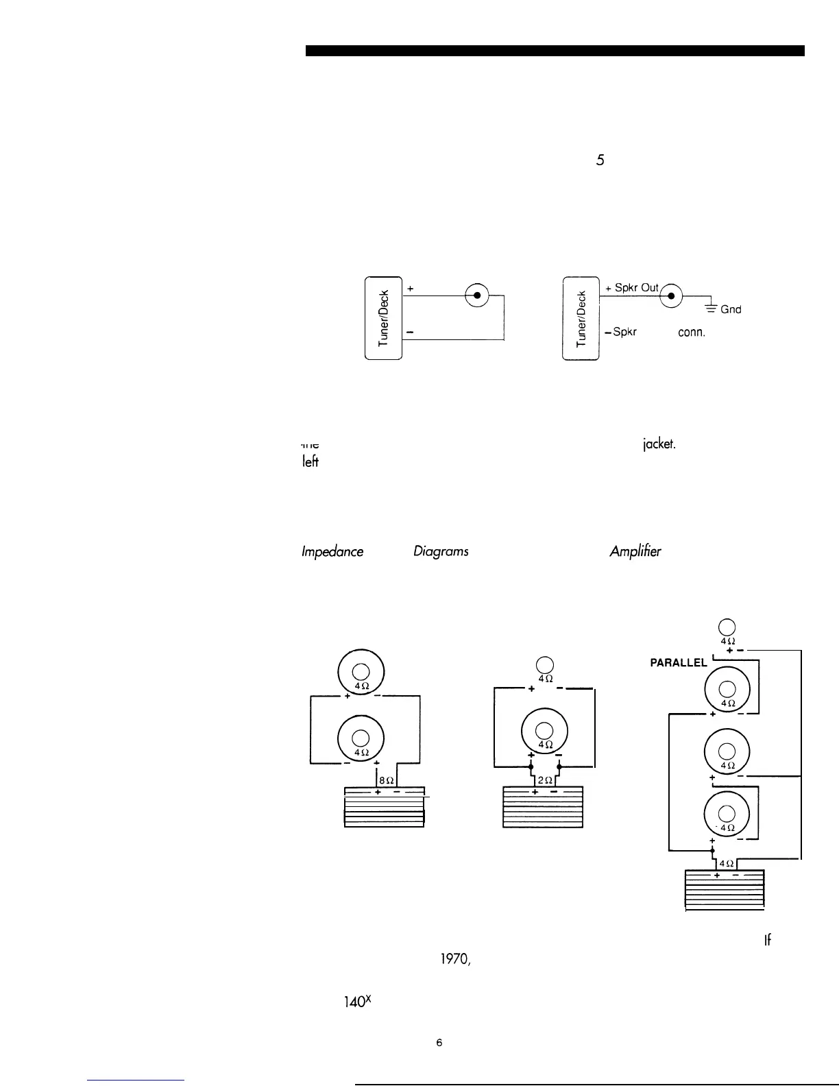
Once you determine the type of output your head unit has, follow the appropriate diagram
below for hookup.
If you have an equalizer or
low level
crossover network(s), these components will be inserted
between your head unit and the amplifier(s). Refer to the manuals of those items for the
proper connection.
/
\
5
+
Spkr Out
6
f-J-=3g@-&G”,
e
g
?
-
Spkr Out
O-
l-l
5
?
-
Spkr Out: no
corm.
\
/
STANDARD
BTL
Output Connections
Use Soundstream High Definition speaker cable (such as Speaker 120 or 160) or an
equivalent
for best results. The terminals of your loudspeakers are marked for polarity, and
the speaker wire should be coded by color or markings on the
iacket.
Be sure to connect the
ieft
and right h
c
annels with the same polarity. Loudspeaker manufacturers are not very
consistent in their polarity markings, so if you have loudspeakers of different types
connected to the same amplifier terminal, verify correct polarity by ear. Correct polarity
produces the most bass response while incorrect produces less bass and a strangely
dislocated
image on
mono material.
For your specific hookup, please carefully review the
lmpedunce
Hookup Diagrams
that
follow, as well
as the
Amp/%er Configuration
Diagrams
at the
end of this manual.
Impedance Hookup Diagrams
SERIES
PARALLEL
Power Connections
0
0
4R
i
+
--
~
0
0
4Q
+
-
2R
iis
+
-
0
0
451
SERIES
+
-
Your amplifier can only be operated from 12 volt negative ground electrical system.
If
your
car was produced before 1970, or if you have any doubts, make sure of the type of electrical
system your car has prior to attempting installation.
The MC
1
40x may draw up to 20 amperes and the MC245 may draw up to 30 amperes, if
6