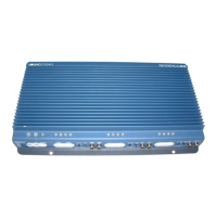
10
INSTALLATION STEP 5
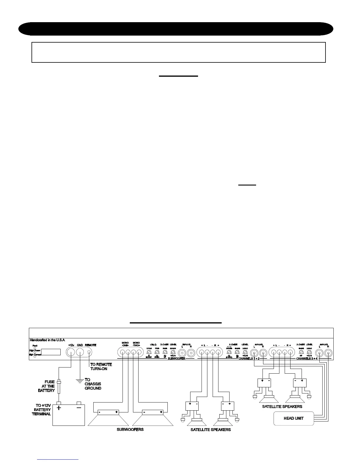
WIRING DIAGRAM
WIRING
POWER AND GROUND
To assure maximum output from the Reference705, use high quality, low-loss power and ground
cables. The Reference705 will accept up to 4 gauge power and ground cables, which is the only
size recommended.
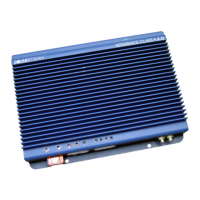
CIRCUIT BREAKERS/FUSES
EXTERNAL
Like all car audio amplifiers, the Reference705 must be protected with a fuse or circuit breaker
located within 18” of the battery. This will prevent a fire in the event of a shorted cable. The
value of the circuit breaker or fuse should be between 60 and 80 amps.
INTERNAL
The Reference705 is fused on its front panel with a 40 amp Maxi-fuse. In the event of a blown
power supply fuse, the “Fault” indicator on the front panel will light. Never replace the fuse with
a higher value than what is supplied. This may result in amplifier damage and will void the
warranty!
REMOTE TURN-ON
Connect the turn-on lead from the source unit to the “Remote” input on the amplifier. When +12
volts is received, the amplifier will turn on.
SIGNAL CABLE
Depending on your application, you may use one to three pairs of signal cables to drive your
Reference705. Use a high-quality cable that will be easy to install and has minimal signal loss to
guarantee optimum performance.
SPEAKER CABLE
The Reference705 will accept up to 8 gauge speaker cable. Use a high quality, flexible, multi-strand
cable for best performance and longevity. Soundstream Speaker120 (12 gauge) is ideal.