Do you have a question about the Southbend P36N-TTT and is the answer not in the manual?
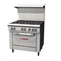
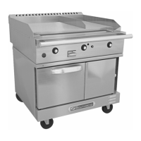
The oven base is a Southbend model TVGS/12WC gas range convection oven that is rated heavy duty for commercial use.
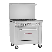
The range top is a Southbend Model P36N-TTT 36" wide split griddle with separate cooking areas.
Convection ovens require connection to a supply of electricity. The appliance, when installed, must be electrically grounded.
A serial plate located inside the lower front panel of the oven base indicates the type of gas the unit is equipped to burn.
There must be adequate clearance between the unit and combustible construction for safety and ventilation.
Shows dimensions for Top View, Rear View, Side View, and Front View of the unit.
Improper ventilation can result in personal injury or death. Ensure proper airflow for combustion and cooling.
All containers should be examined for damage before and during unloading. Inspect for any apparent or concealed damage.
Raise oven sufficiently to allow clearance for the legs or casters to be attached. Ensure unit is level after installation.
For appliances with casters, install a restraint kit to limit movement and prevent disconnection.
Appliance must be electrically grounded. Connect 120V units via plug or 208/240V units via terminal block.
Connect gas supply according to local codes and national standards. Ensure adequate supply and test for leaks.
Verify all connections, clearances, and levelness. Ensure restraint is properly installed for units with casters.
Remove rust preventative, turn on power and gas, light pilot, and break-in griddle surfaces.
Complete installation by cleaning surfaces and ensuring manual is available. Shut off gas/electricity if not in immediate service.
Details on lighting the pilot, controlling griddle temperature, and proper usage for cooking.
Instructions for operating the convection oven, including power, fan mode, and temperature controls.
Explains the functions of the Power Switch, Cook Temperature Control, Fan Mode, Heat-On Indicator, and Top Surface Ignition.
Optimal cooking time and temperature depend on load size, recipe, and moisture content.
Do not overload the oven; the size of the load that can be cooked satisfactorily depends on the product.
Tips for optimal performance, including pre-heating, rack placement, and air circulation.
Table listing common cooking problems and their potential causes and solutions for convection ovens.
Turn power off, cool oven, remove racks, wash interior surfaces with mild detergent, and clean control panel.
Clean motor area, louvered panels, and primary air holes for accumulated grease or lint.
Have unit cleaned and adjusted by a qualified service technician twice a year. Examine and clean venting system.
Instructions for removing dirt, grease, and heat tint from stainless steel surfaces.
Proper care to avoid damage, including using a griddle brick for cleaning and avoiding steel wool.
How to remove the top valve panel to access internal components for adjustments or service.
Lubrication schedule for door chains, sprockets, and casters for smooth operation.
Procedure to check and adjust the gas pressure regulator for natural gas or propane.
Procedure to calibrate griddle thermostats by checking and adjusting temperature settings.
How to adjust griddle burners for proper flame and pilot adjustment for stable operation.
Instructions to adjust the door chain mechanism for proper left and right door opening and closing.
Procedure for qualified technicians to adjust oven temperature settings using potentiometers.
Lists symptoms, possible causes, and corrective actions for common operational issues.
How to access control panel components and use the shut-down switch for troubleshooting.
Location and procedure for checking or replacing fuses on 208/240V models.
Step-by-step instructions for replacing the blower wheel in the oven.
Schematic of the electrical wiring for 120 Volt models.
Schematic of the electrical wiring for 208-240 Volt models.