Step 3. Configure Memory
Your board comes with four DIMM sockets, providing support for up to 1GB of main memory
using DIMM modules from 8MB to 256MB. For 66MHz front side bus CPUs use 12ns or
faster memory; for 100MHz front side bus CPUs use 8ns (100MHz, PC100 compliant)
memory.
Memory Configuration Table
Number of
Memory Modules
DIMM 1 DIMM 2 DIMM 3 DIMM 4
1 1
st
2 1
st
2
nd
3 1
st
2
nd
3
rd
4 1
st
2
nd
3
rd
4
th
RAM Type SDRAM
Memory Module
Size (MB)
8/16/32/64/128/256 Mbytes
Note:(1) 256 MB memory modules only available on PC registered DIMM.
(3) Do not install unbuffered and registered memory modules together.
Important:
It is of prime importance that you install DIMM modules as outlined in the table
above in order to preserve signal integrity on 100MHz front side bus systems.
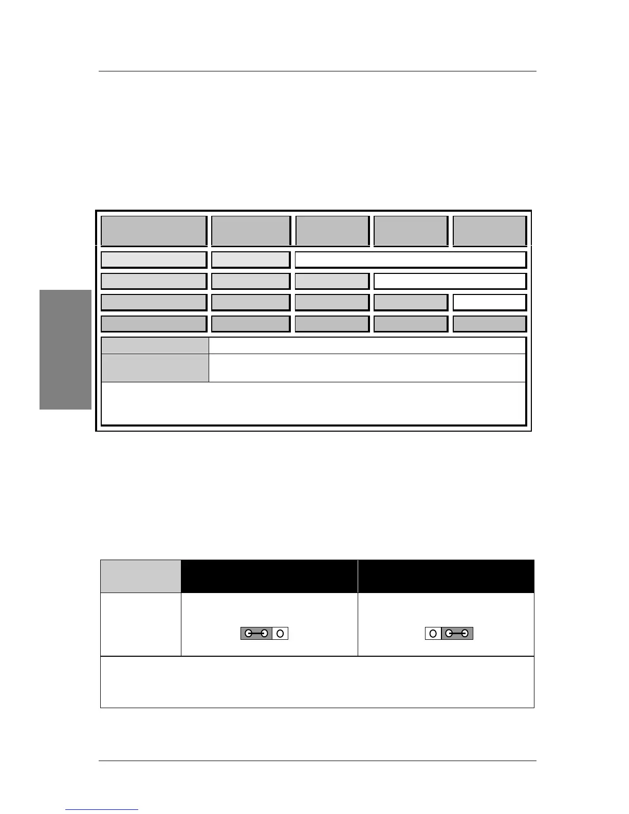
Step 4. Enable/Disable Power-On by Keyboard (JP10)
You can choose to enable the Power-On by Keyboard function by shorting pin 1-2 on jumper
JP10, otherwise, short pin 2-3 to disable this function.
Power-On by
Keyboard
Enable Disable
JP10 Setting
Short pin 1-2 to enable the
Power-On by Keyboard function.
Short pin 2-3 to disable the
Power-On by Keyboard function.
Important: When using the Power-On by Keyboard function, please make sure the
ATX power supply can take at least 700mAmp load on the 5V Standby lead (5VSB) to
meet the standard ATX specification.
 Loading...