Before we get into installing and using the Pro Micro, let’s quickly look at
the board – examine its inputs, outputs, and other hardware quirks.
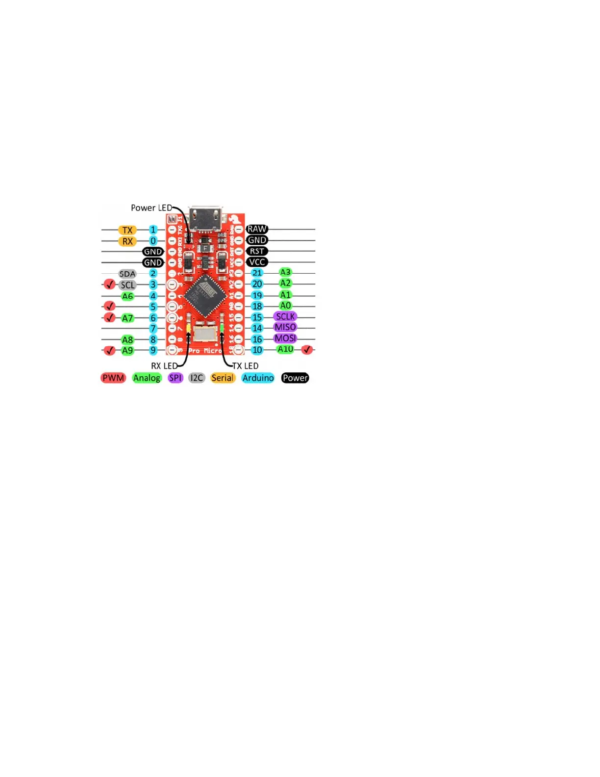
The Pinout
All of the Pro Micro’s I/O and power pins are broken out to two, parallel
headers. Some pins are for power input or output, other pins are dedicated
I/O pins. Further, the I/O pins can have special abilities, like analog input.
Here’s a map of which pin is where, and what special hardware functions it
may have:
Delving a little further into which pins do what…
Power Pins
There are a variety of power and power-related nets broken out:
• RAW is the unregulated voltage input for the Pro Micro. If the board
is powered via USB, the voltage at this pin will be about 4.8V (USB’s
5V minus a schottkey diode drop). On the other hand, if the board is
powered externally, through this pin, the applied voltage can be up to
12V.
• VCC is the voltage supplied to the on-board ATmega32U4. This
voltage will depend on whether you’re using a 3.3V/8MHz Pro Micro
or a 5V/16MHz version, it’ll be either 3.3V or 5V respectively. This
voltage is regulated by the voltage applied to the RAW pin. If the
board is powered through the ‘RAW’ pin (or USB), this pin can be
used as an output to supply other devices.
• RST can be used to restart the Pro Micro. This pin is pulled high by
a 10k&Ohm; resistor on the board, and is active-low, so it must be
connected to ground to initiate a reset. The Pro Micro will remain “off”
until the reset line is pulled back to high.
• GND, of course, is the common, ground voltage (0V reference) for
the system.
Page 3 of 2