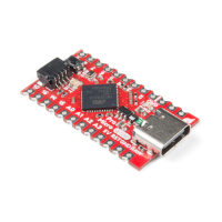
I/O Pins
The Pro Micro’s I/O pins – 18 in all – are multi-talented. Every pin can be
used as a digital input or output, for blinking LEDs or reading button
presses. These pins are referenced in the Arduino IDE via an integer value
between 0 and 21. (The A0-A3 pins can be referenced digitally using either
their analog or digital pin number).
Nine pins feature analog to digital converters (ADCs) and can be used as
analog inputs. These are useful for reading potentiometers or other analog
devices using the
analogRead([pin]) function.
There are five pins with pulse width modulation (PWM) functionality, which
allows for a form of analog output using the
analogWrite([pin], [value]) function. These pins are indicated on-board
with a faint, white circle around them.
There are hardware UART (serial), I C, and SPI pins available as well.
These can be used to interface with digital devices like serial LCDs, XBees,
IMUs, and other serial sensors.
The Pro Micro has five external interrupts, which allow you to instantly
trigger a function when a pin goes either high or low (or both). If you attach
an interrupt to an interrupt-enabled pin, you’ll need to know the specific
interrupt that pin triggers: pin 3 maps to interrupt 0, pin 2 is interrupt 1, pin 0
is interrupt 2, pin 1 is interrupt 3, and pin 7 is interrupt 4.
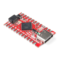
On-Board LEDs
There are three LEDs on the Pro Micro. One red LED indicates whether
power is present.
The other two LEDs help indicate when data is transferring over USB. A
yellow LED represents USB data coming into (RX) the the Pro Micro, and a
green LED indicates USB data going out (TX).
3.3V or 5V? 8MHz or 16MHz?
Pro Micros come in two flavors, which vary by system voltage and
operating frequency. The standard 5V Pro Micro runs at 16MHz, and is
very comparable to an Arduino Leonardo, while the 3.3V version of the Pro
Micro runs at half the speed (to remain in the safe operating zone at the
lower voltage) – 8MHz.
The operating voltage of your Pro Micro determines the maximum allowable
voltage on any of the I/O pins. For example, if you have a 3.3V Pro Micro,
don’t interface it with something that outputs 5V.
2
Page 4 of 2