SPHINX Project Twelve Service Manual
14
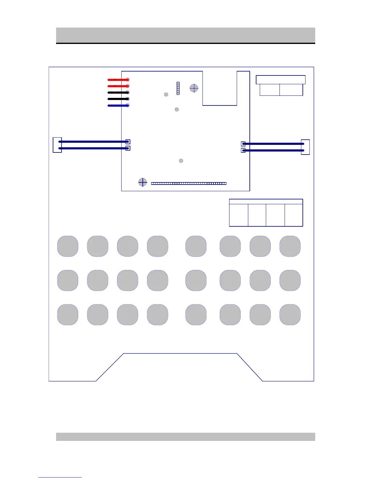
Schematic layout of project 12 with securityprint
Project Twelve main board
Security Print
Large Connector
screw
screw
Attached to heatsink
PTC-connector
PTC-connector
Input wires
Small connector
Pin 1
Pin 22
pin 1
pin 6
Pin assignment
Pin 1 - input
Pin 2 - input Pin 5 + input
Pin 3 gnd
Pin 4 gnd
Pin 6 + input
Positive BALANCED IN (red)
Positive UNBALANCED IN (red)
Ground BALANCED IN (black)
Ground UNBALANCED IN (black)
Negative BALANCED IN (blue)
Pin 21 0 V
Pin 22 0 V
Pin 20 2 V
Pin 13 2 V
Pin 14 0.7 V
Pin 15 60 V
Pin 16 0 V
Pin 17 0 V
Pin 18 0 V
Pin 7 0 V
Pin 8 0 V
Pin 9 0 V
Pin 10 0 V
Pin 11 0 V
Pin 12 15 V
Pin 1 5 V
Pin 2 -2 V
Pin 3 -60 V
Pin 4 0 V
Pin 5 -15 V
Pin 6 0 V
Pin 19 0 V
Large connector Pin Voltage
Small connector (audio in)
Pin 1
Pin 5
Bal.
Offset
BIAS