9
IM-P403-47 AB Issue 7
1
2
3
4
5
6
7
8
9
10
11
12
1
2
3
4
5
6
7
8
9
10
11
12
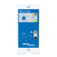
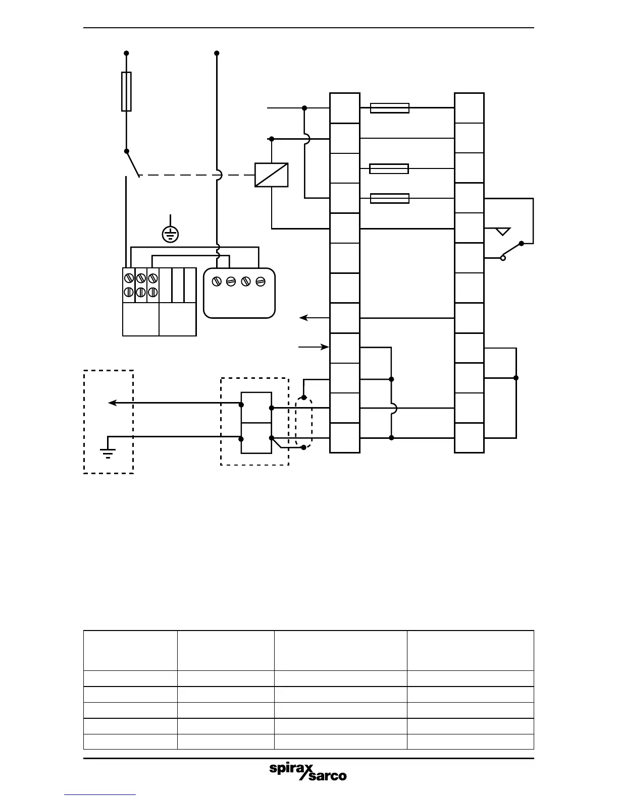
Note: The UL version of the BC1100 is supplied with flying leads already attached. A proprietary
terminal block is required to connect the controller to the field wiring.
Wiring must be run directly between terminal block and controller, and should not be close to other
control wiring.
Ensure correct isolation is provided between low voltage mains supply and Class 2 supply to the
actuator.
Fig. 5 Wiring diagram - UL version used with a 24 Vac BCV30
*
BC1100
* Red
* Blue
* Orange
Brown
Grey
Yellow
White
Black
3 A max.
1 A max.
3 A max.
Field wiring
terminal
block
24 Vac
Class 2
supply
3 A
N/O
Relay
110 Vac
(220 Vac)
No earth
connection on
24 Vac version
3 4 5
C1
C2
Not
used
Link
Link
NY1Y221
0/4 - 20 mA output
Junction box
(if required)
Black
White
L
N
L
High
TDS
Low
TDS
Relay is
shown in
the power
off position
N
110 Vac
(220 Vac)
supply)
Blue
Red
Screen
Sensor and
chamber
Probe
tip
Plugtail
and lead
Blue wire internally connected
to the probe body and earth
Do not connect Terminal 9 + 10 + 12
to any other earth.
Ensure resistance from probe body to
pipework/boiler shell is less than 1 W.
Maximum water Maximum cable length Maximum cable length
conductivity
Maximum cable
2 core cable 4 core cable
at 25°C
resistance
(single cores) (2 cores in parallel)
12 000 µS/cm 0.11 W 6.25 m (20.5 ft) 12.5 m ( 41.0 ft)
8 000 µS/cm 0.17 W 9.50 m (31.0 ft) 19.0 m (62.3 ft)
4 000 µS/cm 0.35 W 19.00 m (62.3 ft) 38.0 m (124.6 ft)
1 500 µS/cm 0.90 W 50.00 m (164.0 ft) 100.0 m (328.0 ft)
<1 200 µS/cm - 100.00 m (328.0 ft) 100.0 m (328.0 ft)
Table 2 - Maximum cable lengths
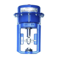
BCV30
Blowdown
valve