10
IM-P403-47 AB Issue 7
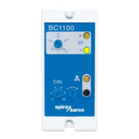
6. Commissioning
Note: Calibration must only be carried out when the blowdown valve is open.
Press and hold down the purge button to open the valve.
1. Measure the TDS or conductivity of the boiler water. The Spirax Sarco MS1 conductivity meter
is a suitable instrument for this purpose.
2. Turn the 'SP' (set point) potentiometer to match the measured boiler water conductivity.
3. With the boiler at operating temperature, press and hold the purge button until the blowdown line
and valve reach boiler temperature.
4. Without releasing the purge button, turn the coarse (left hand) then the fine (right hand) CAL
potentiometers until the '-' green LED just goes off and the '+' amber LED just comes on.
5. Release the purge button.
6. Turn the set point potentiometer to the required conductivity level, as recommended by the boiler
manufacturer.
This will be the conductivity level at which the blowdown valve will open.
5.2 Wiring notes
Maximum cable length from the controller to the sensor varies according to the controller
conductivity range setting.
If multiple cables or alternative larger cable is used, any cable length up to 100 m (328 ft)
is permissible as long as the maximum cable resistance does not exceed the values shown
in Table 2, page 9. For conductivity ranges below 1 200 µS/cm, the recommended cable
only should be used, with no more than two cores in parallel.
Caution: Mains supplies must be on the same phase (single phase, max 264 V).
To wire the controller to purge every half hour of boiler firing, connect terminal 3 to the burner
ON switch (live when burner on).
To wire the controller to purge every half hour, whether the burner has fired or not, link controller
terminals 1 and 3. The 1 A fuse in Figure 4 is then not required.
If the conductivity sensor is mounted in the boiler shell, no purge is required, so leave terminal 3
unwired. The purge switches, (4, 5, and 6), shown on page 6, may be left in any position.