8
IM-P403-47 AB Issue 7
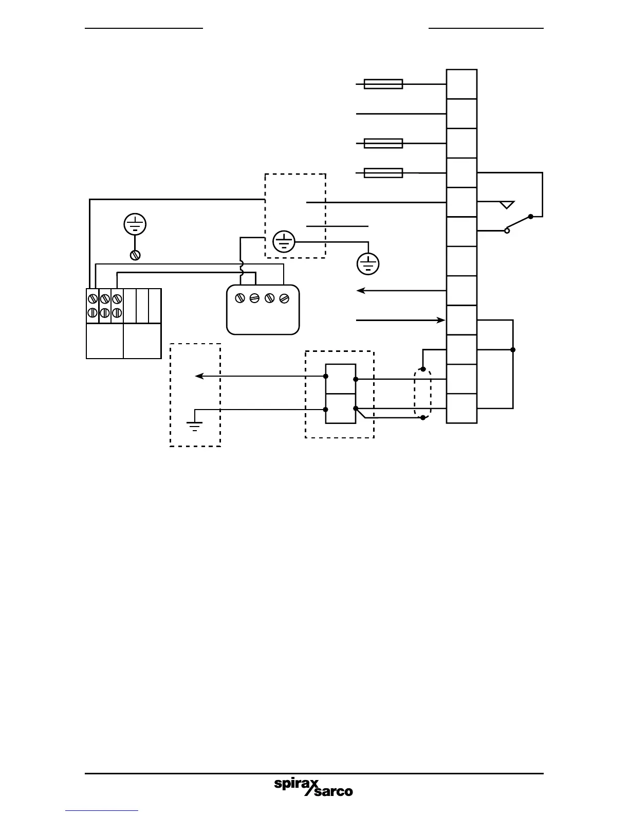
5. Wiring diagram
5.1 Screen connection
An earth current loop is created if a wire or screen is connected between two earth points, which
are at different potential (voltage). If the instructions are followed correctly, then the probe and
controller screen will only be connected to earth at one end.
Note: The probe earth terminal is a functional earth rather than a protective earth.
A protective earth provides protection from electric shock under a single fault condition. This
product has double insulation and therefore does not require a protective earth.
A functional earth is used in order for the product to operate. In this application, the earth
(pipework
/
tank
/
boiler shell) is used as the common of the probe. It also provides sink
/
drain
for any electrical interference.
Ensure that the screen is connected to the earth terminal of the probe and to the common terminal
of the controller.
Ensure the common terminal of the controller is not internally earthed. (All Spirax Sarco boiler
controls are internally isolated from earth).
The common terminal of the controller must only be earthed via the probe.
CAUTION:
Do not connect the common terminal to an earth local to the controller. To do so may
induce an earth current loop, which may reduce the performance or damage the product.
1
2
3
4
5
6
7
8
9
10
11
12
Fig. 4 Wiring diagram - standard version
Low TDS
High TDS
Blue
Red
+
L
N
N
0/4 - 20 mA output
Screen
BCV30
Blowdown
valve
Solenoid valve BCV1/BCV20
Junction box (if required)
L
Live burner input (max. 264 V) L
N
Mains
Select
voltage
internally
3 A max.
1 A max.
1
2
Relay is
shown in
the power
off position
3 A max.
BC1100
3 4 5
C1
C2
Not
used
Link
Link
NY1Y221
No earth
connection
on 24 Vac
version
Sensor
and
chamber
Probe
tip
Plugtail
and lead
Blue wire
internally connected
to the probe
body and earth
Do not connect
Terminal 9 + 10 + 12
to any other earth
For 'Wiring notes',
see page10.
Ensure resistance from probe body to
pipework/boiler shell is less than 1 W.