IM-S24-15 CH Issue 4
12
Note: Before actioning any installation, observe the ‘Safety information’ in Section 1.
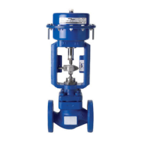
Referring to the Installation and Maintenance Instructions, name-plate and Technical
Information Sheet, check that the product is suitable for the intended installation:
3.1 Check materials, pressure and temperature and their maximum values. Do not exceed
the performance rating of the valve. If the maximum operating limit of the product
is lower than that of the system in which it is being fitted, ensure that a safety device
is included in the system to prevent overpressurisation.
3.2 Remove protective covers from all connections.
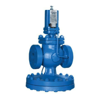
3.3 Determine the correct installation situation and the direction of fluid flow. The valve
should preferably be installed along a horizontal pipeline with the valve mounted above
the pipe. When mounting an actuator to the valve body, the actuator Installation and
Maintenance Instructions must be followed.
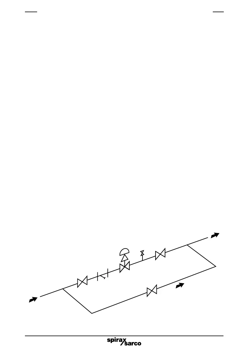
3.4 Bypass arrangements - It is recommended that isolating valves be fitted upstream
and downstream of the control valve, together with a manual bypass control valve.
This enables the process to be controlled manually using the bypass valve while the
pneumatic valve is isolated for maintenance.
3.5 Support pipework should be used to prevent stresses being exerted on the valve
body.
3.6 Ensure adequate space is provided for the removal of the actuator from the valve body
for maintenance purposes:
3.7 Isolate connecting pipework. Ensure it is clean from dirt, scale etc. Any debris entering
the valve may damage the PTFE head seal preventing a tight shut-off.
3.8 Open isolation valves slowly, until normal operating conditions are achieved.
3.9 Check for leaks and correct operation.
3. Installation and commissioning
Isolating
valve
Strainer
Bypass
Control
valve
Isolating
valve
Bypass valve
(piped horizontally)
AVV*
* Anti-vacuum valve recommended for steam installations.
Fig. 1
 Loading...