14
3. Installation
See separate Installation and Maintenance Instructions for the control valve. For details of
differential pressures associated with the Spira-trol
TM
valves refer to the relevant actuator
Technical Information (TI) Sheet.
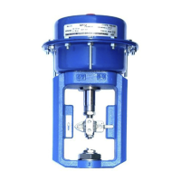
The actuators should be installed in such a position as to allow full access to both actuator
and valve for maintenance purposes. The preferred mounting position is with the actuator
and valve spindle in the vertical position above or below the horizontal pipework. The air
supply to the actuator must be 'dry and free from oil'. For high temperature conditions,
insulate the control valve and pipework to protect the actuator.
Note: If the actuator is to be fitted onto an older style valve, an adaptor ring will be required.
Contact Spirax Sarco for further information.
Warning: The actuator housing must only be pressurized on the opposite side of the
diaphragm holding the springs. The housing vent cap must be left unrestricted.
3.1 Fitting the PN9100E, PN9200E, PN9300E or PN9400E
actuator to a valve (Figures 4 and 5):
-
Remove the front and rear clamp (13 and 14). Then remove the valve adaptor (11).
-
Fit the valve adaptor (11) onto the valve spindle then manually push the valve plug to
its closed position. Caution: Two female threads must be visible inside the adaptor
when fitted to the valve spindle.
-
Apply the control signal pressure required to bring the spindle to mid-travel position
(Figure 5). Place the actuator yoke over the valve spindle and locate it onto the bonnet
shoulder. Hand tighten the mounting nut.
-
Apply the minimum signal pressure + 0.1 bar maximum to the bottom of the actuator,
and then adjust the connector (10) so that it touches the valve adaptor (11), then tighten
the lock-nut (25).
-
Release the control air signal. Fit the front and rear clamps (13 and 14) as shown in
Figure 5.
-
Fit the locking screws and nuts (26 and 27) loosely - 2 Nm (1.5 lbf ft).
-
Operate the actuator and valve over its full travel four times to ensure alignment.
-
Tighten the mounting nut to the recommended torque:
For the M34 nut: 70 Nm (52 lbf ft) and 80 Nm (59 lbf ft) for the stainless steel valve.
For the M50 nut: 100 Nm (74 lbf ft)
For the M70 nut: 160 Nm (119 lbf ft)
-
Tighten the lock-nut to the recommended torque:
For the M8 stem: 10 Nm (7.5 lbf ft)
For the M12 stem: 20 Nm (15 lbf ft)
For the M30 stem: 40 Nm (30 lbf ft)
 Loading...