26
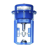
5.3 PN9000R spring-retract
5.3.1 Diaphragm kit - How to fit:
Note: Items 9 and 28 do not apply to the PN9400 actuator.
-
Remove the actuator from the valve as described in Section 5.1.
Note 1: There are 3 off longer housing screws (23) which are fitted to safely allow spring
decompression. These should be removed last after all other screws are removed and
should be loosened evenly to prevent distortion of the housing.
-
Lubricate the threads of the three long hex. head screws with a PTFE based grease
before releasing the tension in the springs.
-
Loosen and remove the short housing screws and nuts (22, 23 and 24).
-
Holding each nut with a spanner, rotate the three long hex. head screws a few turns at
a time. Remove the screws and upper housing (2).
-
Using a spanner to hold the actuator spindle (6), loosen and withdraw the bolt (21).
-
Taking care not to damage the 'O' ring (9) fitted between the diaphragm support plate
(3) and spacer (8), remove the washer (28) and the diaphragm (4).
-
Refit the new diaphragm (4) reassembling all items in reverse order. It is
recommended that Loctite 243 be applied to the upper thread of the spindle (6) prior
to tightening. Ensure spring or springs are correctly seated. Using a spanner to hold
actuator spindle (6) and tighten the bolt (21). Refer to Table 1, for the recommended
tightening torques.
-
Refit the upper housing (2) and securing nuts and screws (22, 23 and 24).
Note 2: Tighten the housing securing screws evenly to avoid distortion. 3 off longer
housing screws (22) are provided on some spring ranges to cater for longer springs. If
supplied, these should be positioned 120° apart and tightened evenly prior to fitting the
remaining bolts.
Table 1 Recommended tightening torques
Actuator series
Screws and nuts
(Items 22, 23 and 24)
Bolt
(Item 21)
Size Torque Size Torque
N m lbf ft N m lbf ft
PN9100 M6 7 5.2 M12 40 29.5
PN9200 M10 35 26.0 M12 40 29.5
PN9300 M10 35 26.0 M12 40 29.5
PN9400 M10 60 44.0 M16 40 29.5
 Loading...