Spirent C1 and C2 Installation Instructions
System Description
Spirent C1 and C2 Installation Instructions | 17
PN 71-008959 Rev A April 2020
SPT-C2 4 x 10G/5G/ 2.5G/1G/100M Copper and SPT-C2 4 x 802.11AX WiFi
2.4GHz and SPT-C2 8 x 802.11AX WiFi 5GHz (NIC-63 and NIC-70-V2)
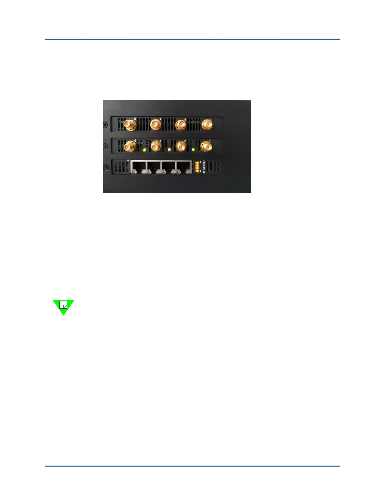
The connector panel is shown in Figure 11.
Figure 11. SPT-C2 4 x 10G/5G/ 2.5G/1G/100M Copper and SPT-C2 4 x 802.11AX WiFi
2.4GHz and SPT-C2 8 x 802.11AX WiFi 5GHz (NIC-63 and NIC-70-V2)
The network data cables (customer supplied) connected to these ports must be as follows:
• Ethernet CAT-5 cable for the management port (Eth0)
• For test ports (1-4) [For NIC-63]
• Copper: RJ45 connector, Ethernet CAT-5e or better cable
• For test ports (1-8) [For NIC-70-V2]
• SMA connector, 50 OHM RF Cable for Conductive Mode
• SMA connector, SMA Male RF Antenna for OTA Mode
Note: Refer to the Spirent C1 and C2 Quick Reference for additional details about the
SPT-C2 cables and connectors.