Spirent C1 and C2 Installation Instructions
System Description
10 | Spirent C1 and C2 Installation Instructions
PN 71-008959 Rev A April 2020
System Description
The SPT-C1/SPT-C2 hardware is maintenance-free and should not be disassembled.
Servicing the units yourself jeopardizes your warranty.
Connector Panel
This section shows the connector panels and describes the necessary cabling. SPT-C1
supports NIC configurations for the test ports, as listed in Table 1 on page 7.
SPT-C2 connector panels and cables are described on page 16. SPT-C2 supports NIC
configurations for the test ports, as listed in Table 2 on page 9.
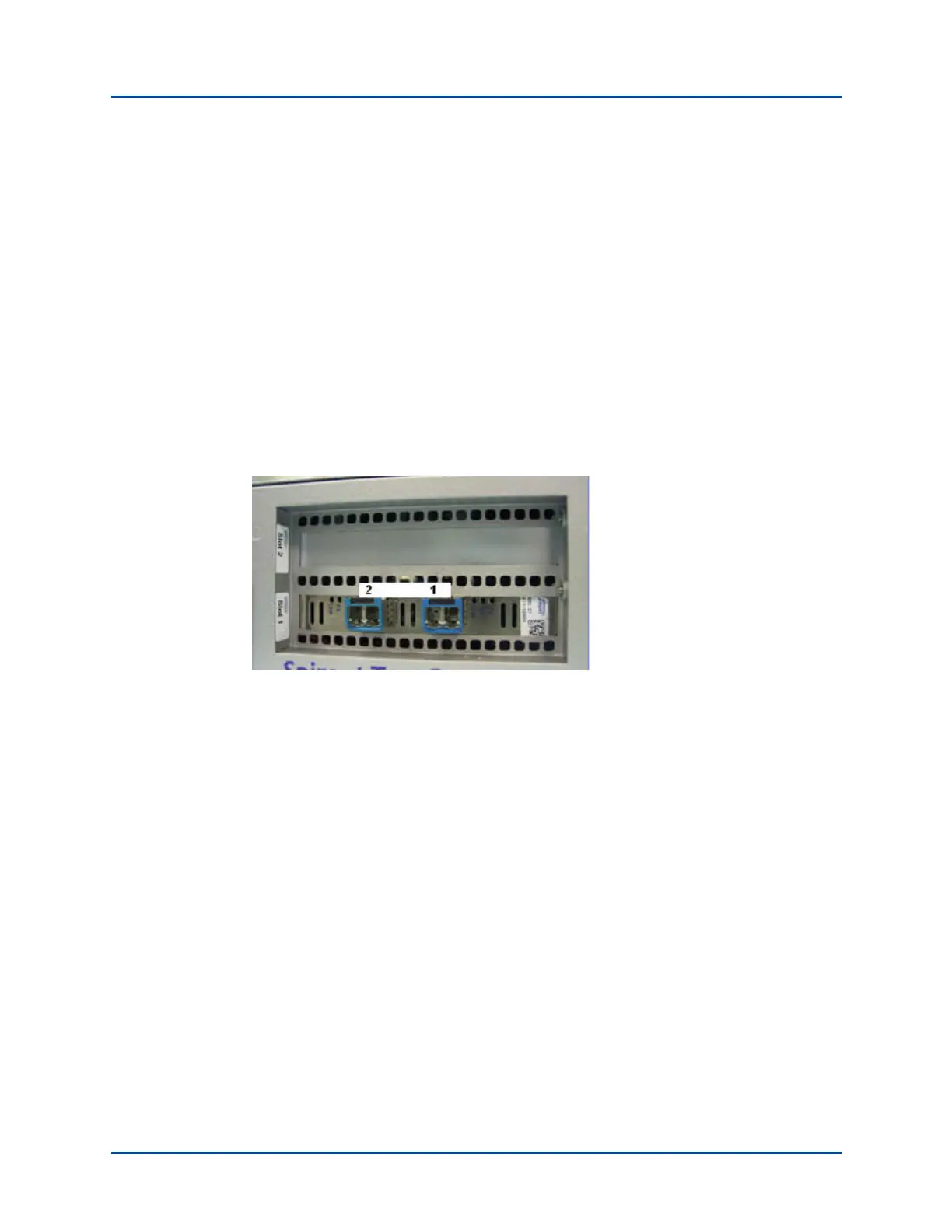
SPT-C1 2 x 10GbE
The SPT-C1 2 x 10GbE connector panel is shown in Figure 2.
Figure 2. SPT-C1 2 x 10GbE Connector Panel
The network data cables (customer supplied) connected to these ports must be as follows:
• Ethernet CAT-5 cable for the management port (Eth0)
• Depending on the NIC configuration, the following for the test ports:
• Two test ports (1 and 2)
– Fiber: LC Fiber Optic connector, Multi-Mode Fiber (62.5um or 50um) cable.