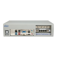
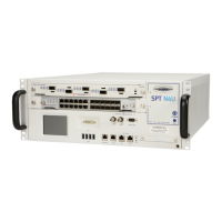
Spirent C1 and C2 Installation Instructions
Requirements
Spirent C1 and C2 Installation Instructions | 7
PN 71-008959 Rev A April 2020
Test Ports
Table 1 lists the NIC configurations for the Spirent C1 test ports.
Table 2 lists the NIC configurations for the Spirent C2 test ports.
The SPT-C1 ports are described under “Connector Panel” on page 10.
SPT-C2 ports are described on page 16.
Refer to the Release Notes for information on supported software applications and
versions. Not all configurations are available for all software applications.
Table 1. NIC Configurations for SPT-C1 Appliance Models
Appliance Model NIC
Part
Number
10/100M Test
Ports
1 GbE Test
Ports
2.5/5GbE
Test Ports
10 GbE Test
Ports
SPT-C1 2 x 10GbE NIC-27
NA NA NA
2
One dual-port
NIC (SFP+
MM fiber)
SPT-C1 4 x 1GbE NIC-33
4*
One quad-port
NIC
(all copper)
4*
One quad-port
NIC
(all copper)
NA
NA
SPT-C1 4 x 1GbE NIC-32
4*
One quad-port
NIC
(all copper)
4*
One quad-port
NIC
(all copper)
NA
NA
SPT-C1 4 x 1GbE NIC-31
NA 4
One quad-port
NIC (optical
for MMF)
NA
NA
SPT-C1 4 x 10/
100M BroadR-
Reach
®
NIC-43
4
One quad-port
NIC (via 2
DE9M
connectors)
NA NA
NA
SPT-C1 2 x 10GbE
and 4 x 1GbE
NIC-27 and
NIC-33
4*
One quad-port
NIC (all copper)
4*
One quad-port
NIC
(all copper)
NA
2
One dual-port
NIC (SFP+
MM fiber)