Spirent C1 and C2 Installation Instructions
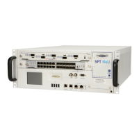
Multiple Chassis and External Time Reference (ETR) Connectors on SPT-C2
Spirent C1 and C2 Installation Instructions | 27
PN 71-008959 Rev A April 2020
External Time Reference Serial DCE
Tabl e 3 lists the pin assignments for the External Time Reference Serial DCE (RJ-45)
connector.
External Time Reference 10MHz
Tabl e 4 lists the pin assignments for the External Time Reference 10MHz (SMA)
connector.
External Time Reference 1 PPS
Tabl e 5 lists the pin assignments for the External Time Reference 1 PPS (SMA) connector.
Table 3. External Time Reference Serial DCE Pin Assignments
PIN Signal
1GPS RTS
2Pin 2,7
3GPS TXD
4 GPS GND
5 GPS GND
6GPS RXD
7Pin 7, 2
8GPS CTS
Table 4. External Time Reference 10MHz Pin Assignments
PIN Signal
1 10MHz CLOCK IN
2 Shield/Signal return
Table 5. External Time Reference 1 PPS Pin Assignments
PIN Signal
1 1PPS CLOCK IN
2 Shield/Signal return