© SprayTECH. All rights reserved. 19
Item Part # Description Quantity
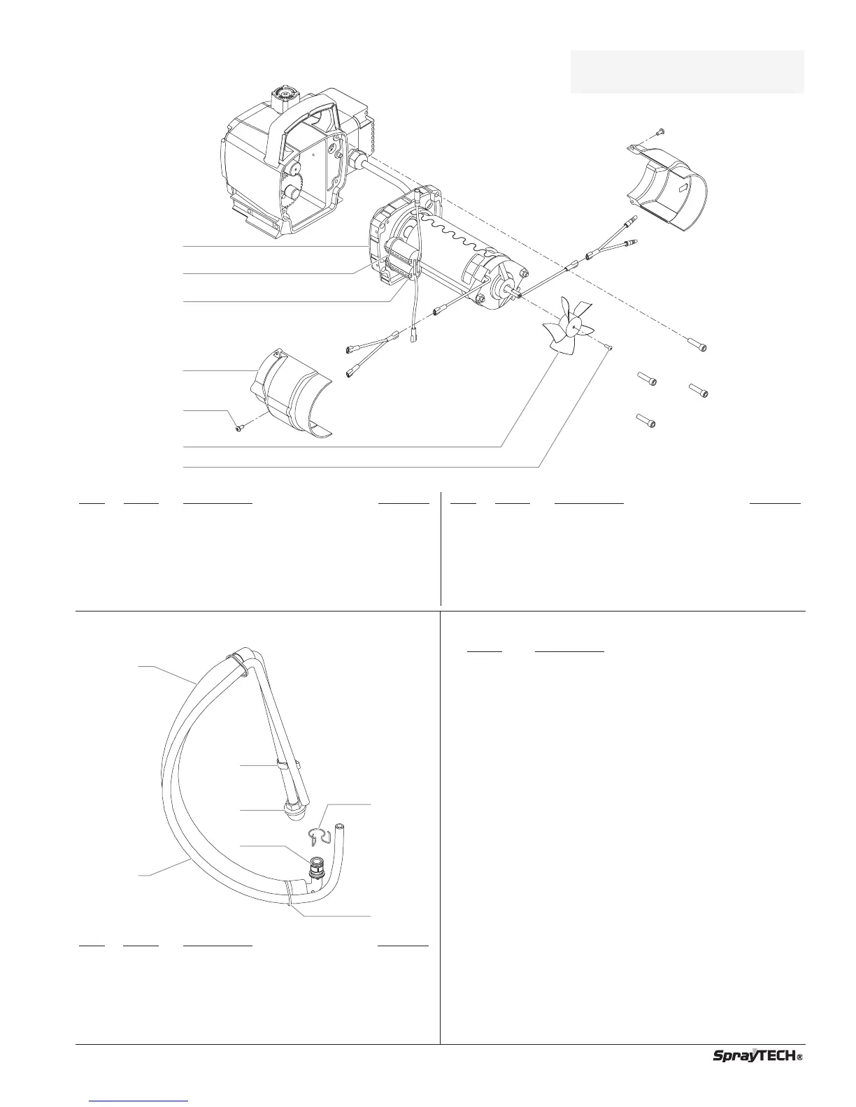
1 0551540 Motor assembly (includes items 2–7
and items 25, 29, and 30 in the
Gear Box Assembly parts list) ....................1
2 0551543 Tie wrap ......................................................2
3 0551514 Capacitor ....................................................1
Item
Part # Description Quantity
4 0508646 Fan shroud..................................................2
5 9802891 Screw..........................................................2
6 0508648 Fan..............................................................1
7 9804916 Fan screw ...................................................1
8 0508653 Double-sided tape (not shown)...................1
0508645 Motor Brush Kit
NOTE: All electrical work should be
performed by a SprayTECH
authorized service center.
Motor Assembly
Suction Set Assembly (P/N 0551104)
Item
Part # Description
Quantity
1 0551437 Siphon tube assembly ................................1
2 0551439 Return hose ................................................1
3 0279459 Hose clip.....................................................1
4 0295565 Inlet screen .................................................1
5 9871105 O-ring..........................................................2
6 9822526 Retaining ring..............................................1
7 9850638 Tie wrap ......................................................2
Labels
Part # Description
0551444 Logo label, front
0551456 Logo label, left
0551464 Logo label, right
0551485 Warning label, explosion/injection
0295805 Shock hazard label
0508330 PRIME/SPRAY knob label
0507856 PRIME/SPRAY label