6
APV_DE3_UK-7_082017.indd
UK
Double Seat Valve
DELTA DE3
Instruction manual: UK - rev. 7
APV
5. Auxiliary Equipment
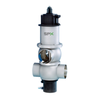
5.1. Valve position indication
Proximity switches to signal the limit positions of the valve shafts
can be installed at the main cylinder if required (fig. 5.1.)
D1 = valve position "closed"
D2 = valve position "open" (only for DN 40 - 50, 1,5” - 2”)
D3 = valve position "open" (only for DN 65 - 150, 2,5” - 6”)
We recommend to use our APV standard types:
operating distance: 5 mm / diameter: 11 mm
If the customer decides to use valve position indicators other than
APV type, we cannot take over any liability for a faultless function.
5.2. Control Unit
The installation of a control unit on the DE3 valve is possible.
Start-up, assembly and dismantling of the different designs are
described in the corresponding instruction manual.
The following different designs are available:
Direct Connect
CU41-M-Direct Connect
08 - 45 - 102/93 ; H320462
AS-interface
extended
CU41-M-AS-i extended 62 slaves
08 - 45 - 112/93 ; H320469
Profibus
CU31-DE3 Profibus
08 - 45 - 003/93 ; H315497
Device Net
CU31-DE3 DeviceNet
16 - 31 - 242/93 ; H209424
- For the installation of the control unit on the DE3 valve an adapter is
required.
5.3. Adater for control unit
CU31 Profibus, CU31 DeviceNet
CU31 - adapter DA3 / DE3
reference number: 000 08 - 48 - 470/93; H314470
- Adater for control unit
CU41 M - Direct Connect, CU41 M - AS-interface
reference number: 000 08 - 48 - 602/93; H320476
D 2
D 1
D 3
fig. 5.1.
 Loading...


