18
APV_DE3_UK-7_082017.indd
UK
Double Seat Valve
DELTA DE3
Instruction manual: UK - rev. 7
APV
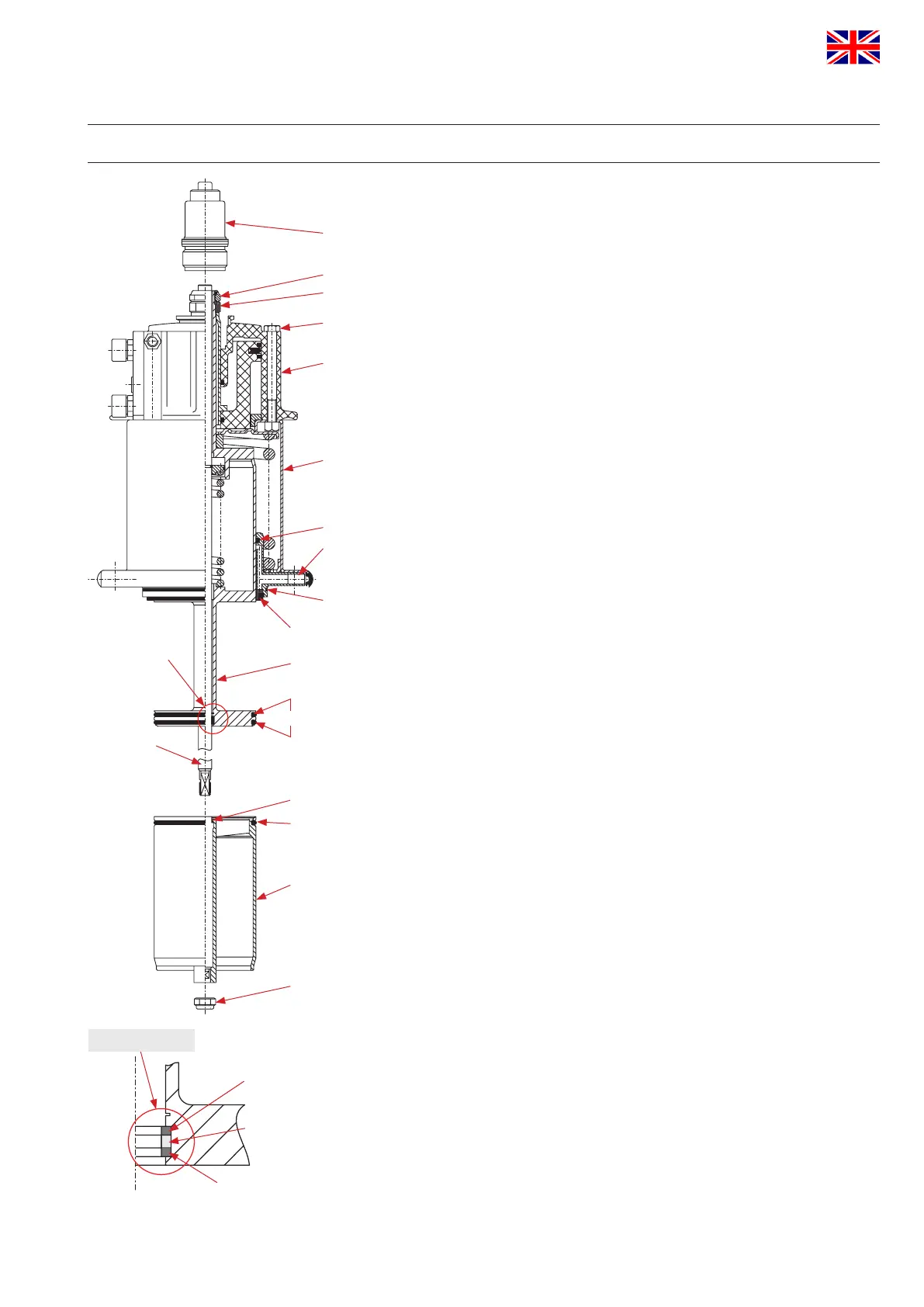
12. Service Instructions
12.4. Installation of product-wetted seals and assembly of valve
All seals and guides can be serviced.
Attention: See to all seals and bearing surfaces in the
product area being carefully greased before their assembly.
(see Lubrication Chart: RN 260.086-1)
1. Install the lower shaft seal (24, 25) in the lower housing anges (see
page 20).
2. Install the quadring (22) and o-ring (37) in the shaft bearing (23).
3. Afterwards insert the rst supporting ring (26), then the quadring
(27) and then the second supporting ring (26) into the upper shaft
(see g. X).
4. Install the o-ring (29) in the lower shaft (3).
5. Insert the 3 seat seals (28) into the grooves of the upper and lower
shafts.
(see page 23 Service Instructions for Seat Seals)
(Seals are symmetric).
6. Slide the upper shaft through the shaft bearing and the actuator.
Screw up the upper shaft and actuator with the safety nut (12) and
safety disc (13).
Tightening torque: Md = 40 Nm
7. Installation of the upper shaft seal (24, 25).
8. First of all, slide the PTFE-ring (24) over the seat of the upper shaft
and place it in the open groove of the shaft bearing (23). Then
press the elastomer ring (25) with the wide side to the front into the
groove.
9. Push in the guide rod (5) from the top until it stops.
10. Fasten the stop screw (11) until stop.
Tightening torque: Md = 25 Nm
11. Slide the lower valve shaft (3) on the guide rod.
Fasten the valve shaft with the safety nut (31).
Tightening torque: Md = 40 Nm
Attention: Check the leakage gap (4 mm) between the
upper and lower valve shaft (see page 14).
- CU design:
Place the CU adapter and fasten it with the inner hexagon screws.
upper
support ring (26)
view X
quadring (27)
lower
support ring(26)
10
11
12
13
14
8
22
23
37
5
28
4
X
29
28
3
31
24, 25
 Loading...


