3
Electrical Connections
Operation of dryers with improper line voltage constitutes
abuse and could affect the dryer warranty.
The dryers are constructed according to NEMA Type 1 electrical
standards. Field wiring must comply with local and national fire,
safety and electrical codes. Installation must be in accordance
with the National Electrical Code. Confirm that your line voltage
is the same as the voltage listed on the dryer data plate. Refer
to Figures 6A, 6B, and 6C electrical schematics.
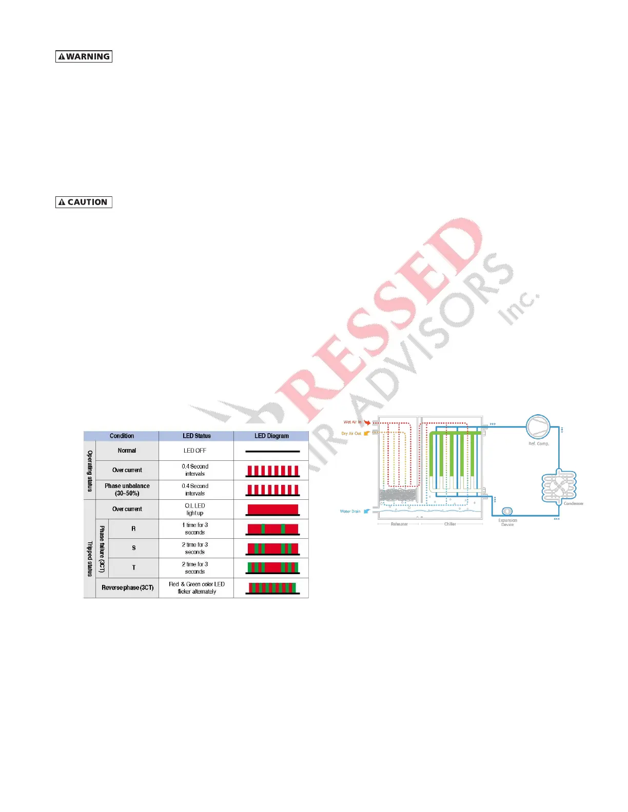
Electronic Over Current Relay (EOCR)
Models FLX 4.5 & FLX 5.5
If the refrigerant compressor is tripped during dryer operation,
or an “E01” error code is displayed in the LCD window, check
the High Pressure Switch or EOCR in the electric box. Red and
green fault LEDs on the EOCR may be used to check the status
of the compressor motor circuit.
A. In case of overcurrent, the red fault LED will illuminate
and flicker at 0.4 second intervals if overcurrent is detected
during motor operation. If the motor contactor is tripped,
the red fault LED will illuminate solid.
B. In case of phase unbalance, the red fault LED will
illuminate and flicker at 0.4 second intervals if the phase
unbalance rate is over 50%.
C. In case of phase failure, the motor contactor is tripped
within 3 seconds of a phase failure in three (3) phase load.
D. In case of reverse phase, the red and green fault LED’s
will flicker alternately.
Refer to the following table for further information.
HOW IT WORKS
Phase Change Mechanism of the FLEX Dryer
1. When the refrigeration compressor and the condenser fan
are running, the cold refrigerant in the chiller (evaporator)
cools the liquid Phase Change Material (PCM) which
gradually solidifies.
2. When the PCM is sufficiently cooled and solidified, the
refrigeration compressor and condenser fan will stop.
3. The compressed air is continuously cooled by the PCM
while the refrigeration compressor is inactive. No power
is consumed during this period.
4. The PCM gradually liquefies as it adsorbs heat from the
compressed air, and when fully melted, the refrigeration
compressor and condenser fan resume to cool the PCM.
Compressed Air flow
The dryers use refrigeration cooling to condense entrained
moisture out of the air stream. Warm saturated air enters the
air-to-air heat exchanger where it is cooled by outgoing cold
air. The inlet air is further cooled in the refrigeration chiller. The
condensate is removed from the air stream by an electronic
drain valve.
The cold, dry air is reheated by incoming warm air as it passes
back through the air-to air heat exchanger. Using the outgo-
ing air to pre-cool the inlet air condenses up to 65 percent of
the moisture out of the inlet air before it reaches the chiller.
Pre-cooling the inlet air reduces the heat load on the refriger-
ant compressor, permitting the use of a smaller refrigerant
compressor.
Figure 2.
Schematic diagram of the compressed air flow and
refrigerant