2
IO
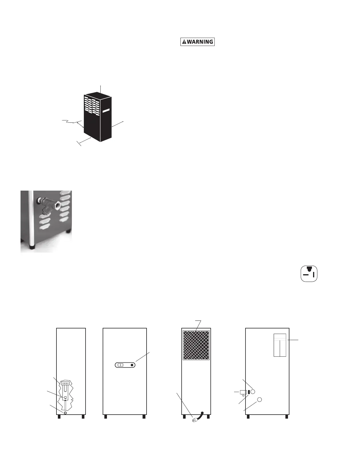
Serial Number
Tag
Ambient Air Filter
Electrical
Connection
Control
Panel
Air Inlet
Connection
Serial
Number
Tag
Drain
Connection
Air Outlet
Connection
Separator and
Integral Filter
Left Side Front BackRight Side
Strainer
(shipped
separately)
Drain
Mechanism
Pipe Nipple
2. Locationinthecompressedairsystem
A. Maximumworkingpressure-250psig,
17.6kgf/cm
2
.Donotexceedunit’sMaximumWorking
Pressure.
1) Formaximumcapacity,installunitinairsystemat
highestpressurepossible(e.g.beforepressure
reducingvalves)
2) Formaximumcapacity,installunitatcoolest
compressedairtemperaturepossible.Maximum
inletcompressedairtemperature:180°F,82°C.If
inletairexceedsthistemperature,precooltheair
byextendingthepipingbetweenthecompressor
and the dryer.
B. AirOutlet-Connectairoutlettodownstreamairlines.
C. By-passpiping-Ifservicingtheunitwithoutinterrupt-
ingtheairsupplyisdesired,pipingshouldincludeinlet
and outlet isolation valves and an air by-pass valve.
D. Condensatedrain-Itisadvisabletoconnectdrain
outlet to the condensate drainage system.
NOTE:Draindischargeisatsystempressure.Drainline
should be anchored to prevent whipping.
1.4 Electrical connections
A. Dryerisdesignedtooperateonpowersupply(voltage)
listedonserialnumbertaglocatedonthebackofthe
dryer.
B. Dryerissuppliedwithanelectricalcord.Installinre-
ceptacleofpropervoltage.
NOTE:Models50and75(115vonly)-Installplug
inreceptacleratedfor20amps.Unitsaresup-
pliedwith20ampplug.
NOTE:Refrigerationsystemisdesignedtoruncontinu-
ouslyandshouldNOTbewiredtocycleon/offwiththeair
compressor.
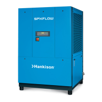
1.0 INSTALLATION
1.1 Location
A. Aircompressorintake-Locateaircompressorsothat
contaminantspotentiallyharmfultothedryerarenot
drawn into the air system.
B. Freeairow-Donotblockeithersideofthecabinet.
Observe minimum installation clearances as shown.
1.2 Mounting
Dryerissuitableforoororshelfmounting.
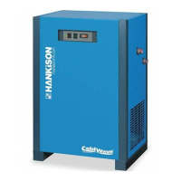
1.3 Piping connections
A. AirInlet-Connectcompressed
airlinefromaircompressorto
air inlet using strainer supplied.
1. Installstrainer(includedin
shippingcarton)priorto
dryer inlet using pipe nipple
supplied or other piping as
required.
NOTE:Observeowdirectionarrowsonstrainer.
NOTE:Installstrainerwhereitiseasilyaccessibleforclean-
ing.
NOTE:Usevibrationdampener,ifvibrationexistsinairline
at inlet to dryer.
Plug