Operating Instructions Form No. 102875
VALVE OPTIONS CONTINUED -
Solenoid Controlled, Air Operated Valve Used With Single- or Double-acting Cylinders
OPERATION
Position "A" (Air Port "A"): Pressure to Port "A". Port "B" to tank.
Position "B" (Air Port "B"): Pressure to Port "B". Port "A" to tank.
NOTE: All ports open to tank during transition
between valve positions.
9594
Figure
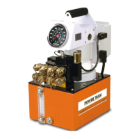
ADJUSTING THE PRESSURE REGULATING CONTROLS
The pressure regulating valve and pressure switch are shown in Figure 6. The pressure regulating valve can be
adjusted to bypass fluid at a given pressure setting while the pump continues to run. The pressure switch can be
adjusted to stop the pump at a given pressure setting. To ensure accuracy and low pressure differential (approx. 300
PSI [21 BAR]) throughout the pressure range (1,000 to 10,000 PSI [70 to 700 BAR] depending on the pump model),
the pressure switch should be used with the pressure regulating valve. The pressure switch must be set at a pressure
lower than the pressure regulating valve to work properly.
Gauge
Single-acting, Spring Return Cylinder: Either fluid port "A" or
"B" must be plugged with a steel plug on the valve. With port
"B" plugged, the sequence of operation is as follows: When
solenoid is energized to position "A", fluid port "A" becomes
pressurized. When solenoid is energized to position "B", fluid
port "A" becomes the return port.
Double-acting Cylinders: When operating double-acting
cylinders, fluid port "A" can be connected to either the advance
or return port of the cylinder and fluid port "B" will be connected
to the remaining port. Sequence of operation is as follows:
When solenoid is energized to position "A", port "A" becomes
pressurized and extends the cylinder and fluid port "B" becomes
the return port. When solenoid "B" is energized, the opposite
of
step 1 happens.
The application in Figure 5 represents a typical set-up using a
control valve and multiple double-acting cylinders (one double-
acting cylinder may be used). Interflow will occur.
If a different set-up or cylinder is being considered, contact your
nearest Power Team facility.
Pump-
mounted
Valve
Sheet No. 6 of 8
Rev 10 Date: 02 Mar 2005
 Loading...