Electrical Connections
- Only use speakers with 4 ohms impedance.
- Do not attach the control panel to the chassis before wiring is complete.
- The maximum current of the Amp Remote trigger is 200mA.
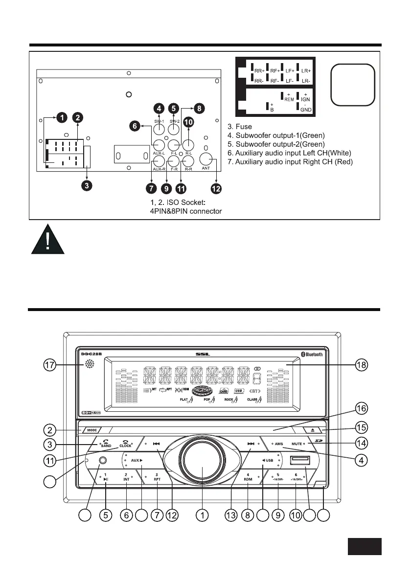
WIRING DIAGRAM
CAUTION
+12V DC
NEGATIVE
GROUND
3
15A
15A
8. Front left PRE-AMP output (White)
9. Front right PRE-AMP output (Red)
10. Rear left PRE-AMP output (White)
11. Rear right PRE-AMP output (Red)
12. Radio antenna socket
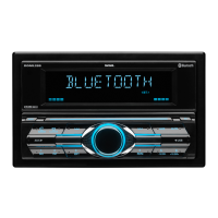
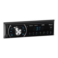
CONTROL PANEL BUTTON LOCATIONS
19 20
21
22
23
24