Hardware layout and configuration UM2408
32/51 UM2408 Rev 2
SB11, SB96, SB15,
SB94 (ARDUINO
®
USART)
ON, ON,
OFF, OFF
ARD D1 (USART TX) and ARD D0 (USART RX) are connected to
PB6 and PB7. Thus PB6 and PB7 on ST morpho connectors
cannot be used.
OFF, OFF,
ON, ON
ARD D1 (USART TX) and ARD D0 (USART RX) are connected to
PD8 and PD9. Thus PD8 and PD9 on ST morpho connectors
cannot be used.
OFF, OFF, OFF, OFF
ARD D1 (USART TX) and ARD D0 (USART RX) are disconnected
from PB6, PB7, PD8, and PD9 on STM32H7.
R40 (VDDA)
ON VDDA and VREF+ on STM32H7 is connected to VDD.
OFF
VDDA and VREF+ on STM32H7 is not connected to VDD and can
be provided from pin 6 of CN7 (Used for external VREF+ provided
by
ARDUINO
®
shield).
JP1 (STLINK NRST)
OFF No incidence on ST-LINK STM32F723IEK6 NRST signal.
ON
ST-LINK STM32F723IEK6 NRST signal is connected to GND (ST-
LINK reset to reduce power consumption).
SB49, SB50 (SWO)
OFF, ON
SWO signal of the STM32H7 (PB3) is connected to ST-LINK SWO
input.
OFF, OFF SWO signal of STM32H7 is not connected.
JP3 (T_NRST)
ON
Board RESET signal (NRST) is connected to ST-LINK reset control
I/O (T_NRST).
OFF
Board RESET signal (NRST) is not connected to ST-LINK reset
control I/O (T_NRST).
SB24, SB13, SB14
(IOREF)
OFF, OFF, ON IOREF is connected to VDD_MCU
OFF, ON, OFF IOREF can be connected to 3V3_PER only on Rev.C
ON, OFF, OFF IOREF is connected to 3V3
SB20 (SDMMC_D0),
SB9 (SDMMC_D1)
ON These pins are connected to ST morpho connector CN12.
OFF
These pins are disconnected from ST morpho connector CN12 to
avoid stub of SDMMC data signals on PCB.
SB54, SB65 (LD1-
LED)
ON, OFF Green user LED LD1 is connected to PB0.
OFF, ON
Green user LED LD1 is connected to D13 of
ARDUINO
®
signal
(PA5).
OFF, OFF Green user LED LD1 is not connected.
ON, ON Forbidden
R74 (LD2-LED)
ON Yellow user LED LD2 is connected to PB7.
OFF Yellow user LED LD2 is not connected.
R75 (LD3-LED)
ON Red user LED LD3 is connected to PB14.
OFF Red user LED LD3 is not connected.
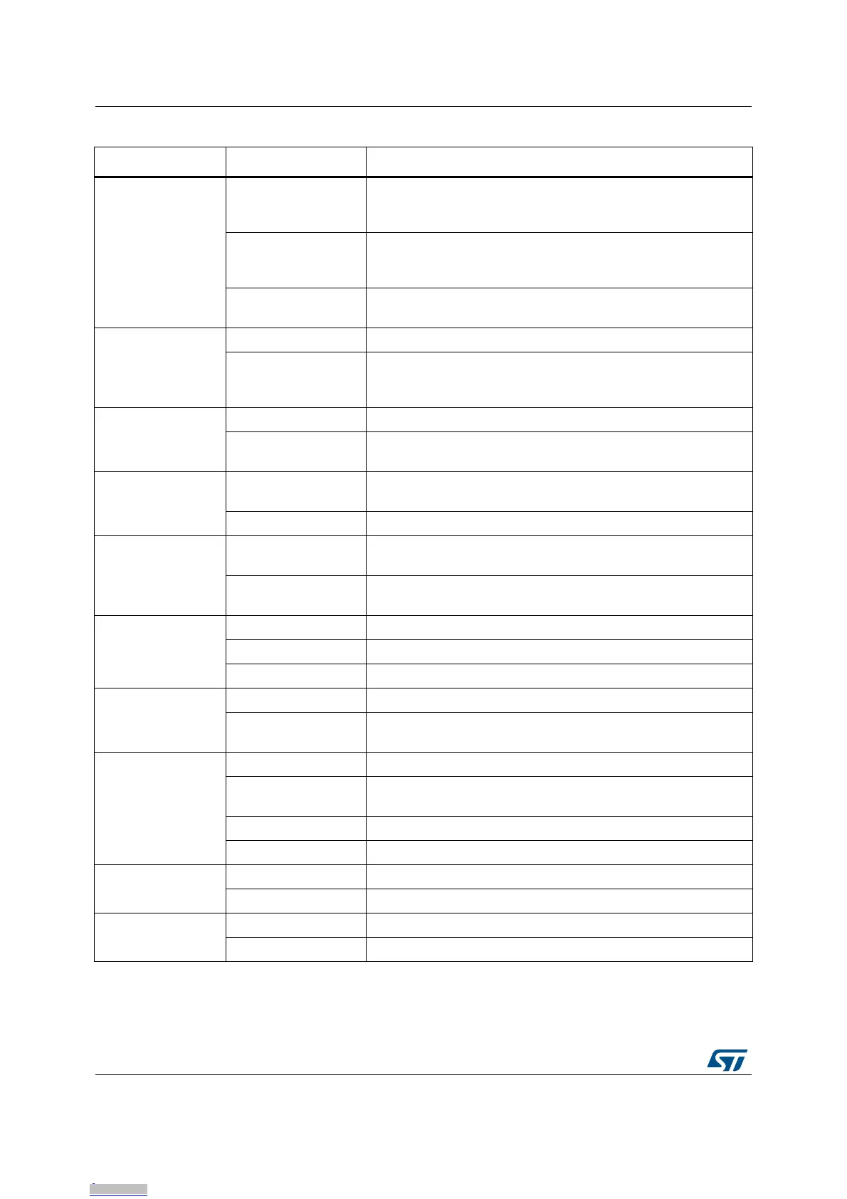
Table 16. Solder bridges (continued)
Bridge State
(1)
Description
Downloaded from Arrow.com.Downloaded from Arrow.com.Downloaded from Arrow.com.Downloaded from Arrow.com.Downloaded from Arrow.com.Downloaded from Arrow.com.Downloaded from Arrow.com.Downloaded from Arrow.com.Downloaded from Arrow.com.Downloaded from Arrow.com.Downloaded from Arrow.com.Downloaded from Arrow.com.Downloaded from Arrow.com.Downloaded from Arrow.com.Downloaded from Arrow.com.Downloaded from Arrow.com.Downloaded from Arrow.com.Downloaded from Arrow.com.Downloaded from Arrow.com.Downloaded from Arrow.com.Downloaded from Arrow.com.Downloaded from Arrow.com.Downloaded from Arrow.com.Downloaded from Arrow.com.Downloaded from Arrow.com.Downloaded from Arrow.com.Downloaded from Arrow.com.Downloaded from Arrow.com.Downloaded from Arrow.com.Downloaded from Arrow.com.Downloaded from Arrow.com.Downloaded from Arrow.com.
 Loading...