5 / 17
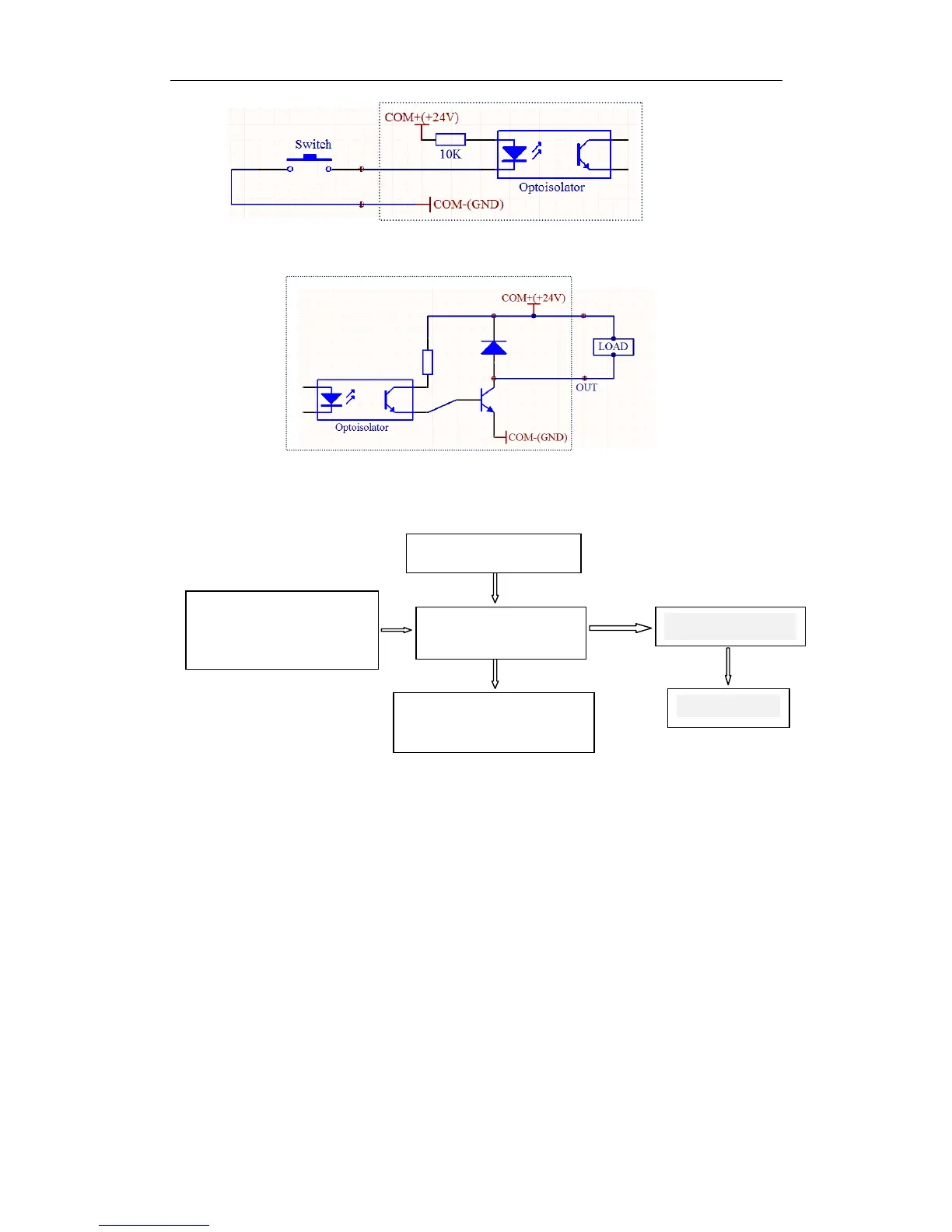
Figure Ⅲ switch input circuit
When the switch is turned on, Input level is low, on the front panel indicator lights, the program
is defined as 0.
Figure Ⅳ switch output circuit
Output of low output, load conduction, front panel indicator lights, the program is defined as 1.
Ⅳ. The controller connection diagram:
Figure Ⅴ controller connection diagram
Ⅴ. The operation flow chart
Controller always operate in one of four states: automatic mode, manual mode, the program edit
mode, parameter setting state. Power or press the Reset, Controller to be run in automatic mode,
the cursor coordinates 0, then you can start the program to run automatically or switch to
manual mode, program editing state and parameter setting status can only switch in manual
mode. Editing completed or parameter setting procedure is completed, press the Quit to return
to manual mode (the program will be saved) ,in manual mode, if you switch to program edit
mode, simply press the Edit button, if you switch to the parameter setting state, press Set more
than 2 seconds.
(Note: The above mentioned Edit, Set, Quit, is the same button, we introduce a feature, the
button's name only choose one, the same below)
OUT1-3
CP CW OPTO
Input devices: External
Start button、Limit switch 、