7 / 17
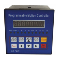
Ⅵ. parameter setting:
Out of the way of parameter setting status is: In manual mode, press Edit and hold the
button for 2 seconds or more , enter the parameter setting state. After parameter setting is
complete, press the Quit button to return to manual mode (parameters will be saved).
Parameters displayed in two rows, the first row shows the name of the parameter, the second
line shows the parameter data.
Parameter changes: After entering the parameter setting state, the first line of the display:
jf------. Former two parameter name in flashing: press∧∨, Will display the next or previous
parameter name, press Enter, Will enter the edit state (next row) parameter data, when the first
bit of data flashing display, press∧∨, data will be changed. press <>, Will move to the next
one to be modified, after the data modification, press Enter Save changes, press Cancel discard
changes and exit.
In short, the set parameters through ∧∨<> "Enter", "Cancel" six buttons to complete the six:
by moving left and right keys to move the cursor to the appropriate position, then the digital
display will beat, and then through the upper and lower keys to change the value: use the Enter
key to enter the data modification status, after the data modification is completed, confirm with
the Enter key to exit or discard the changes with Cancel button. Please refer to the "List of
operational processes."
N
(Hz)
If the set value is less than 400Hz, the system will alarm;
Users can set different off frequencies according to their actual situation
2
Rising and
falling curve
rS- - - - - -
(stripe)
The controller has two internal optimization rising and falling speed curve,L is
a slow curve; H to a faster curve, to select a different rate of rise and fall curve
based on the actual load situation.
3
Backlash
compensation
CC- - - - - -
Mainly used to compensate the rotation mechanism(such as a
screw, gear, etc.) The amount of displacement caused by the backlash
error
compensation is not displayed on the controller.
4
Manual
increment
HL- - - - - -
HL X X X X
X X
1-999999
(pulses
number)
In manual mode, the manual operation is a displacement of the
stepper motor; If the set value is equal to 0, the system will alarm.
5
(Hz)
In manual mode, manual operation is running speed stepper motor; If the set
value is equal to 0, the system will alarm.
6
Back to zero
speed
bF- - - - - -
(Hz)
When zeroing operation, stepper motor speed; If the set value is equal to 0, the
system will alarm
7
A Operation"
entry address
Na- - - - - -
NA XX
00-99
(Line number)
When the program is running, if the "A Operation" signal input port, the motor
for the deceleration stop the program at this interruption, the application
remembers interrupted coordinate values, the program will jump to this line
number specified
by the program at run the program.
8
B Operation"
entry address
nB- - - - - -
nB XX
00-99
(Line number)
When the program is running, such as Gao "B Operation" end signal input, the
motor will slow down to stop the program at this interruption, the application
remembers interrupted coordinate values, the program will jump to this line
number specified by the program run the program.
9
CP X
0、1
CP = O represented as a single pulse output, CP-side rear panel output step
pulse, CW-ended output direction level; CP = I expressed as a single pulse
output, CP-ended output on the rear panel forward step pulse, CW-ended
output inversion step pulse.