UM1724 Rev 14 37/68
UM1724 Hardware layout and configuration
67
6.11 ARDUINO
®
connectors
CN5, CN6, CN8, and CN9 are female connectors compatible with ARDUINO
®
standard.
Most shields designed for ARDUINO
®
can fit the STM32 Nucleo boards.
The ARDUINO
®
connectors on the STM32 Nucleo board support the ARDUINO
®
Uno V3.
For compatibility with ARDUINO
®
Uno V1, apply the following modifications:
• SB46 and SB52 must be ON,
• SB51 and SB56 must be OFF to connect I
2
C on A4 (pin 5) and A5 (pin 6 of CN8).
Caution 1: The I/Os of STM32 microcontroller are 3.3 V compatible instead of 5 V for ARDUINO
®
Uno
V3.
Caution 2: SB57 must be removed before implementing ARDUINO
®
shield with VREF+ power being
provided on CN5 pin 8. Refer to Table 10: Solder bridges for details on SB57.
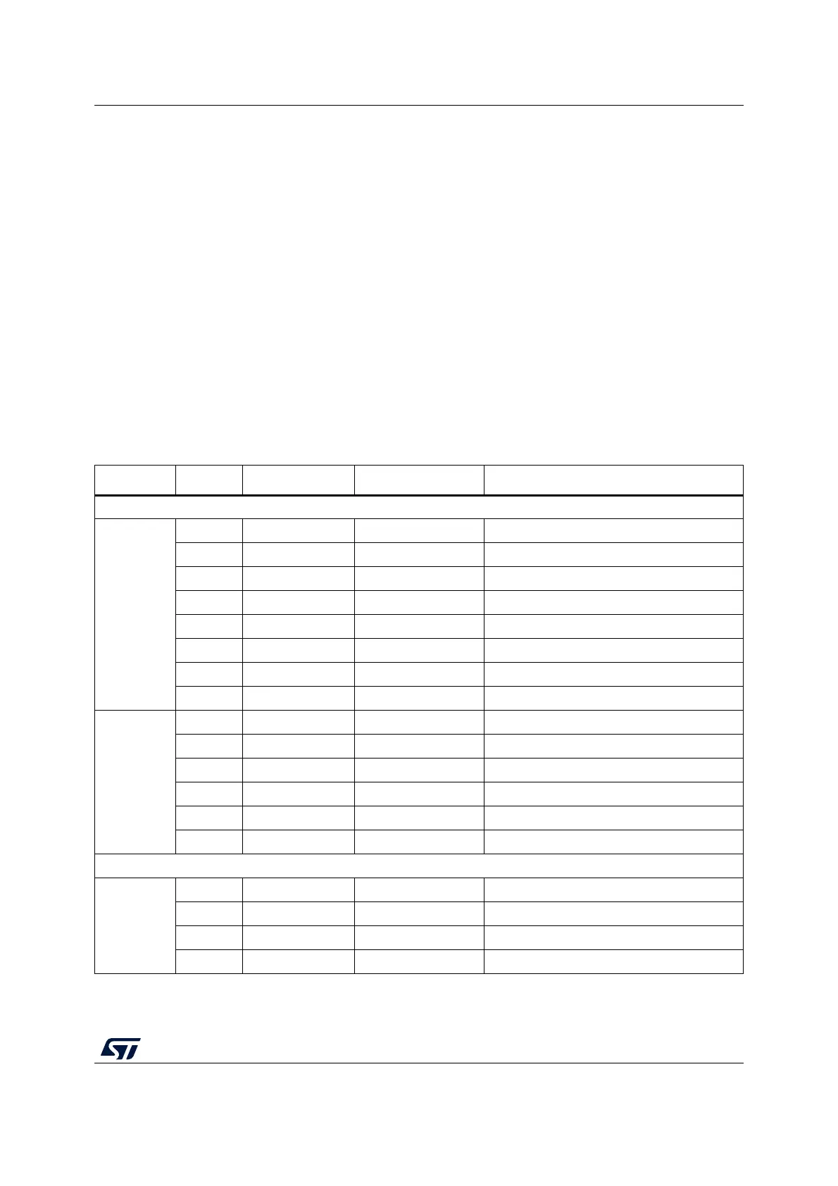
Table 11 to Table 23 show the pin assignment of each main STM32 microcontroller on
ARDUINO
®
connectors.
Table 11. ARDUINO
®
connectors on NUCLEO-F030R8, NUCLEO-F070RB,
NUCLEO-F072RB, NUCLEO-F091RC
Connector Pin Pin name STM32 pin Function
Left connectors
CN6 power
1NC - -
2 IOREF - 3.3V Ref
3 RESET NRST RESET
4 +3.3V - 3.3V input/output
5 +5V - 5V output
6GND - ground
7GND - ground
8 VIN - Power input
CN8 analog
1 A0 PA0 ADC_IN0
2 A1 PA1 ADC_IN1
3 A2 PA4 ADC_IN4
4 A3 PB0 ADC_IN8
5 A4 PC1 or PB9
(1)
ADC_IN11 (PC1) or I2C1_SDA (PB9)
6 A5 PC0 or PB8
(1)
ADC_IN10 (PC0) or I2C1_SCL (PB8)
Right connectors
CN5 digital
10 D15 PB8 I2C1_SCL
9 D14 PB9 I2C1_SDA
8 AREF - AVDD
7GND - ground
 Loading...


