Do you have a question about the ST STM32H743I-EVAL and is the answer not in the manual?
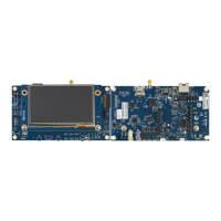
Detailed top-side view identifying key components and connectors on the evaluation board.
Provides mechanical dimensions for the evaluation board with the 5.7-inch LCD daughterboard.
Details on the integrated ST-LINK/V2-1 debugger, its features, and notes on ETM trace.
Instructions for installing the necessary drivers for the ST-LINK/V2-1.
Guidance on how to upgrade the firmware for the embedded ST-LINK/V2-1.
Describes the six possible power supply sources and configuration jumpers.
Details on the clock sources (crystals) used for the microcontroller and peripherals.
Lists the various sources that can trigger a reset on the evaluation board.
Explains how to configure the boot options using switches and jumpers.
Information on the audio codec, DACs, ADCs, and microphone connections.
Details on the USB OTG1 Full-Speed interface and its powering capabilities.
Describes the USB OTG2 High-Speed and Full-Speed interfaces and their configurations.
Information about the RS232 connector (CN2) and its connection to USART1.
Details on the microSD card slot (CN13) and supported SD card standards.
Description of the external I2C connector (CN4) for daughterboard connection.
Details on the Flexible Data Rate CAN (FD-CAN) interface and related jumpers.
Information on the Ethernet PHY, RJ45 connector (CN1), and clock source selection.
Description of SDRAM, SRAM, and NOR Flash memory interfaces.
Details on the implementation of Twin Quad-SPI NOR Flash memory.
Information on the analog input connector (CN5) and potentiometer.
Overview of LEDs, joystick, buttons, and the TFT LCD.
Description of the MFX chip's role as an IO-expander and its I2C interface.
Pinout and description for the Ethernet RJ45 connector.
Pinout and description for the RS232 connector, including ISP support.
Pinout and description for the CAN D-type connector.
Pinout and description for the external I2C connector.
Pinout and description for the analog input-output connector.
Details on the 60-pin headers for daughterboard connection.
Pinout and description for the ETM trace debugging connector.
Pinout and description for the JTAG/SWD debugging connector.
Pinout and description for the external DC 5V power supply connector.
Details on the 40-pin connectors for memory daughterboards.
Pinout and description for the microSD card connector.
Pinout and description for the USB OTG2 High-Speed Micro-AB connector.
Pinout and description for the USB OTG2 Full-Speed Micro-AB connector.
Pinout and description for the USB OTG1 Full-Speed Micro-AB connector.
Pinout and description for the 3.5mm stereo audio jack for headset.
Pinout and description for the 3.5mm stereo audio jack for speaker.
Information about the TFT LCD connector used for display.
Pinout and description for the USB Micro-B connector for ST-LINK.
Pinout and description for MEMS microphone coupon connectors.
| Brand | ST |
|---|---|
| Model | STM32H743I-EVAL |
| Category | Motherboard |
| Language | English |


 Loading...